Connection structure capable of realizing rapid disassembly and assembly, and used for helium gas turbine
A technology for connecting structures and turbines, which is applied in the direction of blade support components, stators, engine components, etc., can solve the problems of difficult disassembly and assembly of the turbine shell and difficult assembly, achieve the safety margin of protection strength, reduce the overall weight and structure simple compact effect
- Summary
- Abstract
- Description
- Claims
- Application Information
AI Technical Summary
Problems solved by technology
Method used
Image
Examples
specific Embodiment approach 1
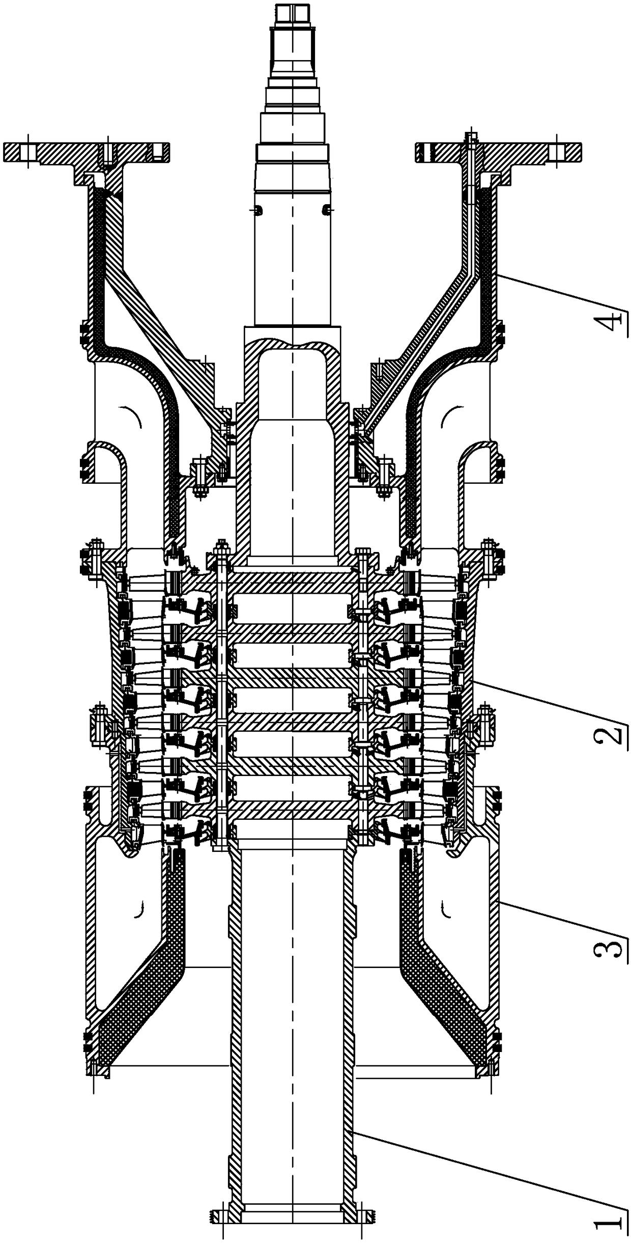
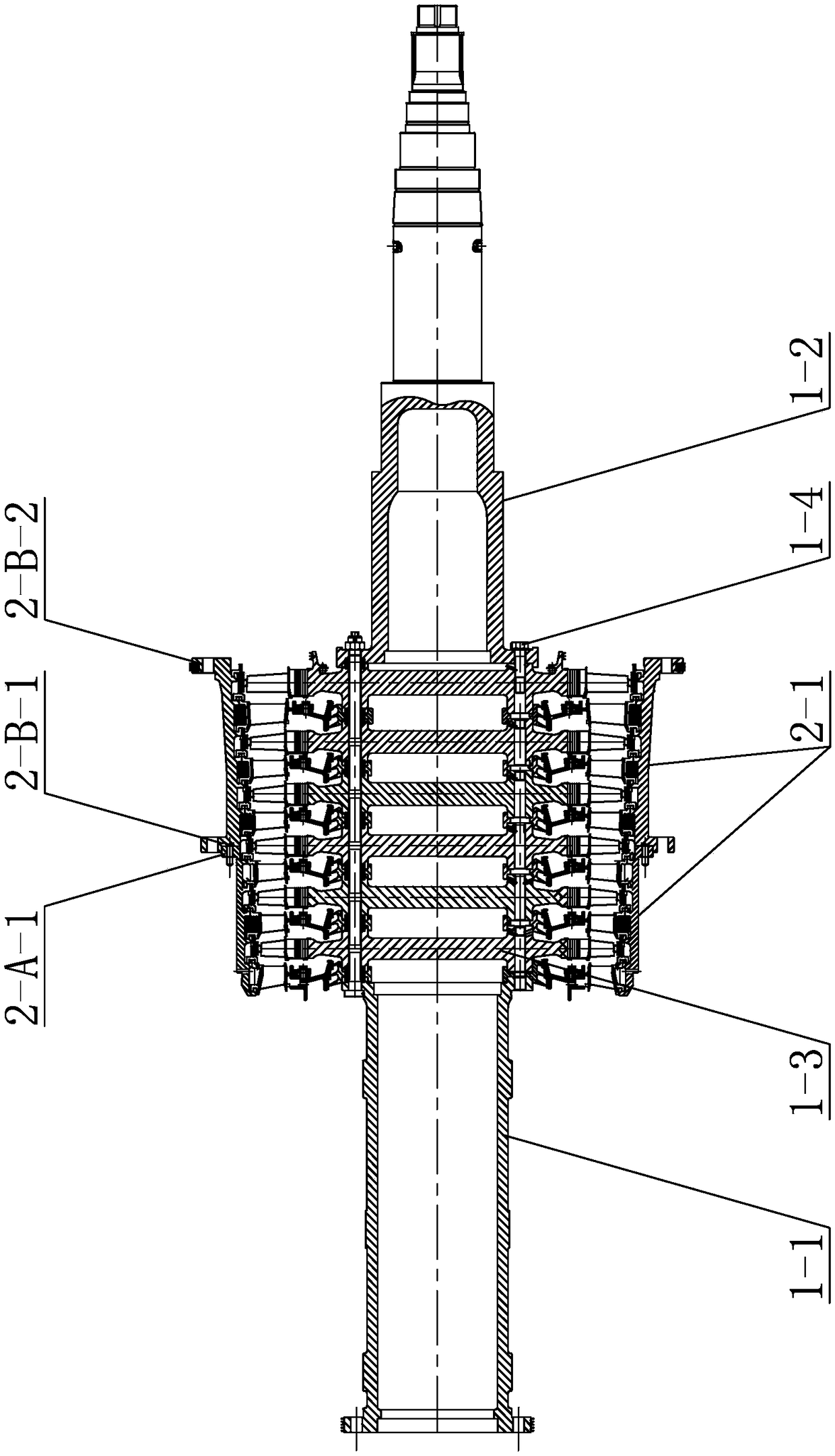
[0031] Specific implementation mode one: combine Figure 1 to Figure 5 Describe this embodiment, a helium turbine connection structure that can be quickly disassembled and assembled in this embodiment, it includes a turbine rotor 1 and a turbine stator 2, the turbine stator 2 is sleeved on the turbine rotor 1, and the two turbine stators 2 The ends are respectively connected with the external steam inlet casing 3 and the steam outlet casing 4,
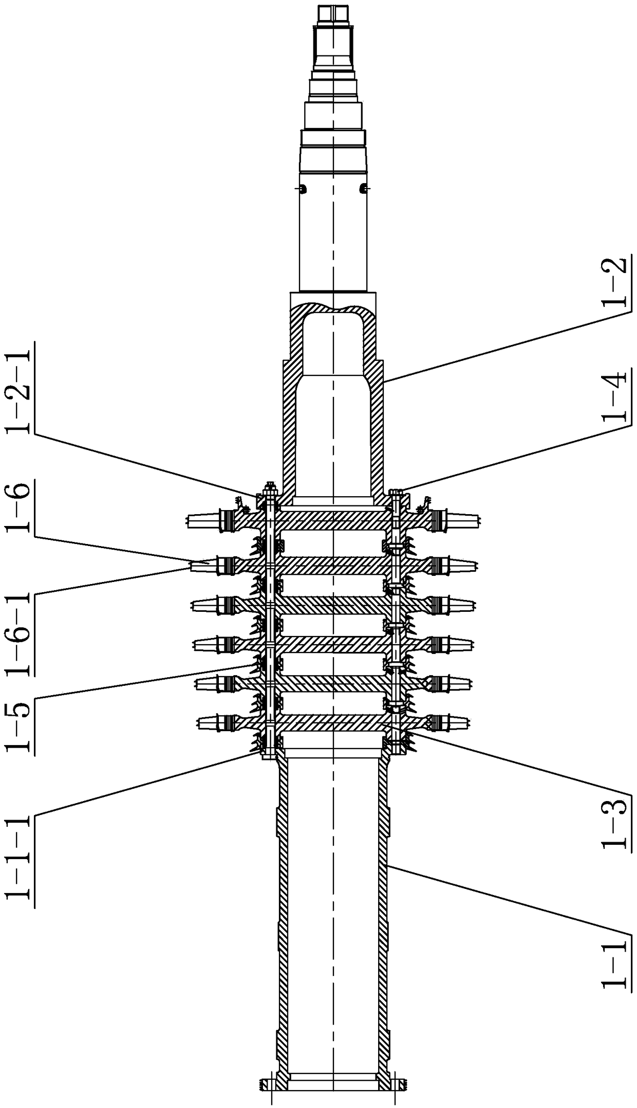
[0032] The turbine rotor 1 includes a turbine front shaft 1-1, a turbine rear shaft 1-2, six rotor discs 1-3 and 2N long stay bolts 1-4, where N is a positive integer greater than or equal to 4,
[0033] The outer diameters of the six rotor discs 1-3 are the same, and N first cooling air circulation holes 1-3-1 are evenly distributed along the circumferential direction on the end face of each rotor disc 1-3, and two adjacent first cooling air circulation holes 1-3-1 Two first bolt holes 1-3-2 are evenly distributed between the air cir...
specific Embodiment approach 2
[0039] Specific implementation mode two: combination image 3 with Image 6 To illustrate this embodiment, the turbine rotor 1 of this embodiment also includes six stepped tooth seal rings 1-5, and a stepped tooth is provided between two adjacent rotor disks 1-3 among the six rotor disks 1-3. Sealing ring 1-5, there is a stepped tooth sealing ring 1-5 between the turbine front shaft 1-1 and the adjacent rotor disc 1-3, six stepped tooth sealing rings 1-5 and six stators The guide vane rings 2-2 are in one-to-one correspondence, and the six stator guide vane rings 2-2 are sealed with the stepped teeth 1-5-3 of the stepped tooth seal ring 1-5,
[0040] The outer diameters of the six stepped tooth seal rings 1-5 are the same, and N second cooling air circulation holes 1-5-1 are uniformly distributed along the circumferential direction on the end face of each stepped tooth seal ring 1-5, and each stepped tooth seal ring The N second cooling air circulation holes 1-5-1 on the rin...
specific Embodiment approach 3
[0042] Specific implementation mode three: combination image 3 with Figure 5 Describe this embodiment, the turbine rotor 1 of this embodiment also includes six moving blade units, each moving blade unit includes a number of moving blades 1-6, the root of each moving blade is provided with mortise teeth, each rotor disc A plurality of tenon grooves 1-3-3 matched with tenon teeth are evenly distributed on the outer circumference of 1-3, and the moving blade is connected with the rotor disc 1-3 through the mutually matched tenon teeth and tenon grooves 1-3-3. Other compositions and connections are the same as those in Embodiment 1 or Embodiment 2.
PUM
 Abstract
Description
Claims
Application Information
 - R&D
- Intellectual Property
- Life Sciences
- Materials
- Tech Scout
- Unparalleled Data Quality
- Higher Quality Content
- 60% Fewer Hallucinations
Browse by: Latest US Patents, China's latest patents, Technical Efficacy Thesaurus, Application Domain, Technology Topic, Popular Technical Reports.
© 2025 PatSnap. All rights reserved.Legal|Privacy policy|Modern Slavery Act Transparency Statement|Sitemap|About US| Contact US: help@patsnap.com


