Air inlet structure of electric propulsion engine

An air intake structure and engine technology, which is applied to machines/engines, mechanical equipment, thrust reversers, etc., can solve the problems of reduced engine body volume and complicated engine propellant supply, and achieve the effect of compact sealing structure

Active Publication Date: 2019-03-01
BEIHANG UNIV
View PDF7 Cites 5 Cited by
  • Summary
  • Abstract
  • Description
  • Claims
  • Application Information

AI Technical Summary

Problems solved by technology

[0003] With the low power of the electric propulsion engine, the volume of the engine body is greatly reduced, and the propellant supply of the engine becomes more complicated

Method used


Image

  • Air inlet structure of electric propulsion engine
  • Air inlet structure of electric propulsion engine

Examples


Embodiment Construction

[0019] Attached below Figure 1~2 Specific embodiments of the present invention will be described.

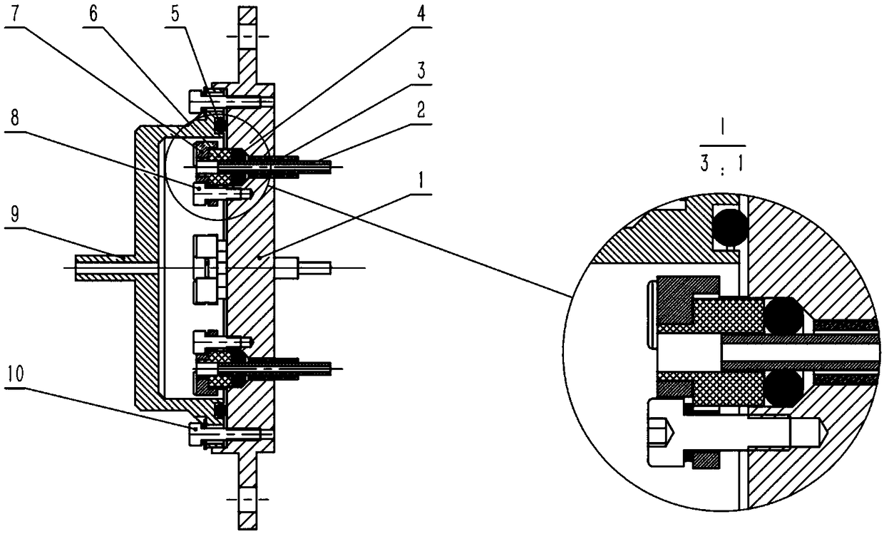
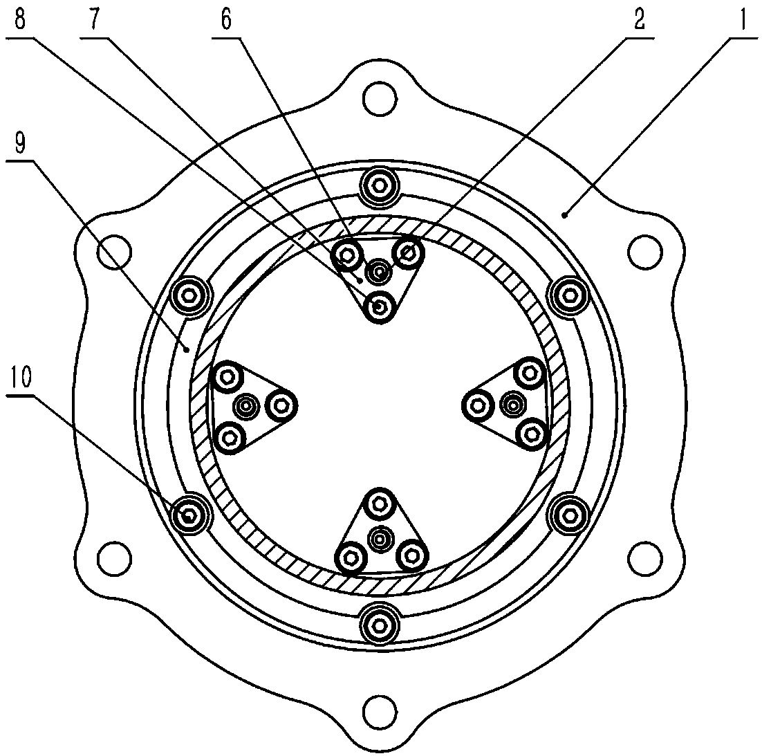
[0020] The present invention is an electric propulsion engine air intake structure, the main components include engine body flange 1, gas distributor pipeline 2, insulating ceramic tube 3, gas distributor pipeline-sealing ring 4, air intake cavity-sealing ring 5. Gas distributor pipeline-ceramic terminal 6, gas distributor pipeline-press sheet 7, gas distributor pipeline-fastening bolt 8, inlet flange 9, connecting bolt 10.

[0021] combine figure 1 , taking the engine body flange 1 as a reference, insert four insulating ceramic tubes 3 from the right side into four 4mm small holes on the engine body flange 1, and the left end surface of the insulating ceramic tube 3 is connected to the engine body flange 1 Align the cone edges.

[0022] combine figure 1 , Insert the four gas distributor pipelines 2 into the four insulating ceramic tubes 3 from the right side, and the left ...


PUM


Abstract

The invention provides an air inlet structure of an electric propulsion engine, relates to the problem of propellant supply of the electric propulsion engine, and belongs to the field of electric propulsion. The volume of the electric propulsion engine body is greatly reduced, and a propellant supply structure of the engine becomes more complicated. Because an engine gas distributor air inlet pipeline has a high discharge voltage and is in a relatively high working temperature range, a propellant supply pipeline outside the engine is difficultly in direct connection with a gas distributor, otherwise the engine is short-circuited. In order to solve the problem, an electric propulsion engine air inlet structure with sealing and insulating functions is designed. Conical surface extrusion is carried out on a gas distributor pipeline-sealing ring, and an air inlet cavity is formed between an air inlet flange and an engine body flange, so that the one-to-four connection mode between an external propellant pipeline and the engine gas distributor pipeline is achieved, and simultaneously the sealing and insulation requirements on the outer wall surface of the gas distributor pipeline and the engine body flange are met.

Description

Technical field: [0001] The invention belongs to the technical field of electric propulsion, and relates to an air intake structure of an electric propulsion engine. Background technique: [0002] As an advanced space propulsion technology, electric propulsion technology has a wide range of applications in spacecraft attitude control, orbit transfer, north-south position maintenance, and repositioning. With the gradual development of micro-satellites, electric propulsion engines are also developing in the direction of low power. Low-power electric propulsion engines have unique advantages in formation flight and position maintenance of micro-satellites. [0003] With the low power of the electric propulsion engine, the volume of the engine body is greatly reduced, and the propellant supply of the engine becomes more complicated. Since the intake pipeline of the engine gas distributor has a high discharge voltage and is in a relatively high operating temperature range, it is...

Claims


Application Information

Patent Timeline
Patent Type & Authority Applications(China)
IPC IPC(8): F03H1/00
CPCF03H1/0006F03H1/0087
Inventor 汤海滨张广川任军学王一白鲁超
Owner BEIHANG UNIV
Why Eureka
Try Eureka