Michelson interferometer image fringe width detection method and system

A technology of stripe width and detection method, which is applied in the direction of instruments, measuring devices, scientific instruments, etc., can solve the problems of high cost and complicated operation of detecting stripe width, and achieve high accuracy, high measurement accuracy and strong portability Effect

Active Publication Date: 2019-03-01
XI'AN INST OF OPTICS & FINE MECHANICS - CHINESE ACAD OF SCI
View PDF3 Cites 4 Cited by
  • Summary
  • Abstract
  • Description
  • Claims
  • Application Information

AI Technical Summary

Problems solved by technology

[0005] The purpose of the present invention is to provide a method for automatically detecting the width of the interference ellipse ring through the interference image to solve the problem of high cost and complicat

Method used


Image

  • Michelson interferometer image fringe width detection method and system
  • Michelson interferometer image fringe width detection method and system
  • Michelson interferometer image fringe width detection method and system

Examples


Embodiment Construction

[0045] The present invention will be further described below in conjunction with the accompanying drawings and specific embodiments.

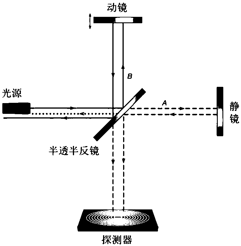
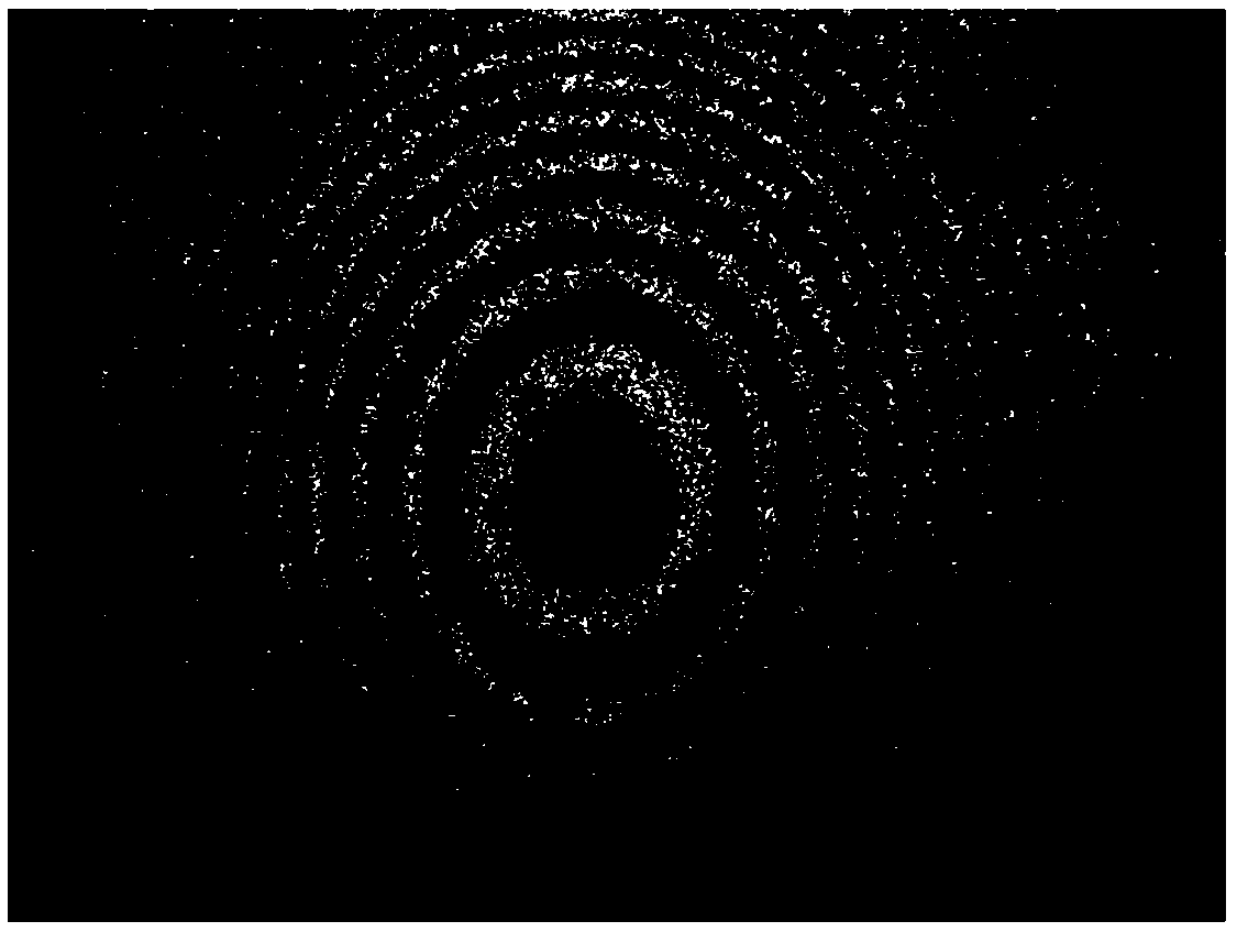
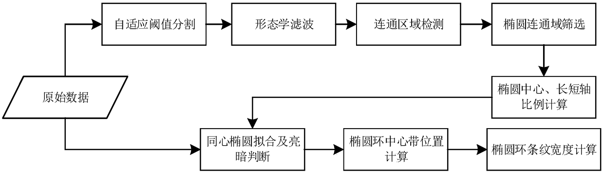
[0046] The invention can automatically detect the position and radius of the interference ellipse ring in the Michelson interferometer image with low signal-to-noise ratio, so as to calculate the interferometer fringe width. Its algorithm is as figure 2 As shown, it specifically includes image preprocessing, interference ellipse ring parameter estimation, interference ellipse ring fitting, fringe width calculation and other processes. The above-mentioned several processes correspond to different stages of algorithm implementation, which are specifically implemented according to the following steps.

[0047] Image preprocessing:

[0048] Step 1: Using an adaptive binary segmentation method, starting from Figure 1b The bright ring pixels are isolated on the low SNR raw image shown.

[0049] Find an appropriate threshold and perform adaptive...


PUM


Abstract

The present invention relates to a Michelson interferometer image fringe width detection method and system. The core technology is that: an interference circular ring is automatically detected throughan interference image, and the light and dark widths of the circular ring are calculated. The method comprises the steps of: adaptive binarization segmentation of the interference image, calculationand screening of a communication area, extraction of an elliptical communication area, determination of the center of the ellipse and the ratio of semi-minor axis length, concentric ellipse fitting and determination of light and dark states, and calculation of the elliptical ring interference fringe state. Through detection of the width of the concentric circular ring, the optical path differencecondition of the Michelson interferometer, the spectral information is inverted and it is confirmed whether the interferometer state is stable or not.

Description

technical field [0001] The invention relates to a method for detecting the annular fringe state of a Michelson interferometer through an image processing algorithm. Background technique [0002] Michelson interferometer (English: Michelson interferometer) is the most common type of optical interferometer. Its principle is that a beam of incident light is divided into two beams by a beam splitter and then reflected back by the corresponding plane mirror, because the frequency of the two beams is are the same, the vibration direction is the same and the phase difference is constant (that is, the interference condition is satisfied), so interference can occur. The different optical paths of the two beams of light in the interference can be realized by adjusting the length of the interference arm and changing the refractive index of the medium, so that different interference patterns can be formed. Interference fringes are tracks of equal optical path difference. If the interfe...

Claims


Application Information

Patent Timeline
IPC IPC(8): G01J9/02
CPCG01J9/02G01J2009/0234G01J2009/0284
Inventor 张耿李思远胡炳樑张周锋张宏建刘欢
Owner XI'AN INST OF OPTICS & FINE MECHANICS - CHINESE ACAD OF SCI
Why Eureka
Try Eureka