Inertial impactor with wetted impaction surface to prevent particle loading effect

A technology of load effect and inertial impact, which is applied in the direction of instruments, scientific instruments, particle suspension analysis, etc., and can solve the problems of particle sampling or monitoring concentration underestimation, impactor interception diameter reduction, etc.

Inactive Publication Date: 2019-03-01
SPRING FOUND OF NCTU
View PDF9 Cites 1 Cited by
  • Summary
  • Abstract
  • Description
  • Claims
  • Application Information

AI Technical Summary

Problems solved by technology

[0004] However, as the sampling time increases, a particle mound or particle deposit will gradually form on the impact plate below the nozzle, so that the subsequent collected particles will hit the previously accumulated particles instead of the impact surface, which

Method used


Image

  • Inertial impactor with wetted impaction surface to prevent particle loading effect
  • Inertial impactor with wetted impaction surface to prevent particle loading effect
  • Inertial impactor with wetted impaction surface to prevent particle loading effect

Examples


Embodiment Construction

[0035] A number of implementations of the present invention will be described below with drawings and words. For the sake of clarity, many practical details will be described together in the following description. It should be understood, however, that these practical details should not be used to limit the invention. In addition, for the sake of simplifying the drawings, some existing structures and elements will be drawn in a simple and schematic way in the drawings.

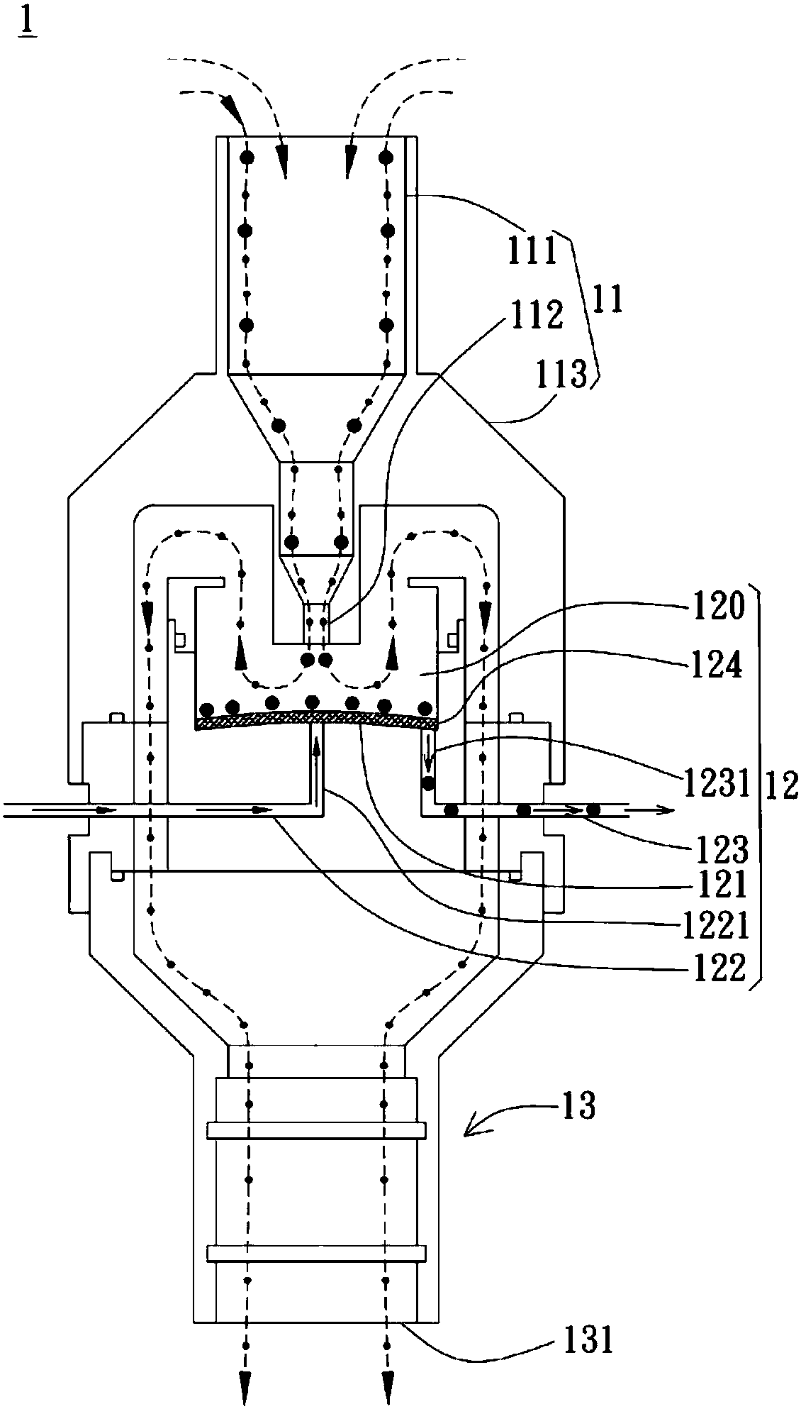
[0036] see figure 1 The particle impactor 1 includes an upper casing 11 , an impact portion 12 and a lower casing 13 connected to each other. The upper casing 11 preferably has a gas inlet 111 , a nozzle 112 connected to the gas inlet 111 , and an outer casing 113 extending downward from the upper casing 11 . The air inlet 111 is used to receive outside air. The impact part 12 is wrapped inside the outer casing 113 and has an impact well 120 , and the cavity surrounded by it corresponds to the nozzle 112 . ...


PUM


Abstract

The invention discloses an inertial impactor with a wetted impaction surface to prevent the particle loading effect. The inertial impactor can prevent the particle loading effect and is composed of anupper shell, an impacting part, and a lower shell. The upper shell is provided with an air inlet and a round nozzle that is connected to the air inlet. The impacting part comprises an impacting well,and the lower part of the impacting well is an impacting surface. The nozzle is right opposite to and is above the center of the impacting surface. The center of the impacting surface is provided with a liquid inlet. Liquid is continuously or intermittently introduced to the impacting surface so as to wet the impacting surface and remove particles, at the same time, the liquid is discharged froma liquid discharge route in the impacting surface, and the lower shell is provided with an air outlet channel, which is connected to a particle sampling or monitoring device.

Description

technical field [0001] The present invention relates to a particle impactor, and more particularly, to a particle impactor that reduces the effects of particle loading effects. Background technique [0002] As more and more nano products come out, nanoparticles may escape or be released during the process of manufacture and use. Many research results show that nanoparticles inhaled by the human body will affect health. In order to assess the health hazards of nanoparticles in the workplace to relevant practitioners, it is necessary to collect nanoparticles of different particle sizes and conduct subsequent component analysis. . [0003] Particle impactor is an existing particle collection device. When the air flow passes through the nozzle and hits the impact plate downward, the air flow makes a 90-degree turn because the gas cannot pass through the impact plate, so it is larger than the specific aerodynamic particle size (or intercepted particle size) particles, which can...

Claims


Application Information

Patent Timeline
IPC IPC(8): G01N15/06
CPCG01N15/06G01N15/0606
Inventor 蔡春进黎氏菊宋荣哲
Owner SPRING FOUND OF NCTU
Why Eureka
Try Eureka