A Constructing Method of Control Flow Graph for Object-Oriented Program

A control flow graph, object-oriented technology, applied in software design and other directions, can solve problems such as difficult migration, and achieve the effect of easy program understanding

Active Publication Date: 2022-02-15
SOUTHEAST UNIV
View PDF2 Cites 0 Cited by
  • Summary
  • Abstract
  • Description
  • Claims
  • Application Information

AI Technical Summary

Problems solved by technology

The existing research results mainly focus on the control flow analysis of structured syntax features and simple exception handling structures, and these research results are difficult to transfer to the construction of control flow graphs of object-oriented programs with complex exception handling structures.

Method used


Image

  • A Constructing Method of Control Flow Graph for Object-Oriented Program
  • A Constructing Method of Control Flow Graph for Object-Oriented Program
  • A Constructing Method of Control Flow Graph for Object-Oriented Program

Examples


Embodiment

[0074] For convenience, it is assumed that there is a simplified source code example:

[0075] Table 1 instance code

[0076]

[0077]

[0078] According to the calculated steps mentioned above, implement them:

[0079] Step An analysis of the corresponding abstract syntax tree according to the above code:

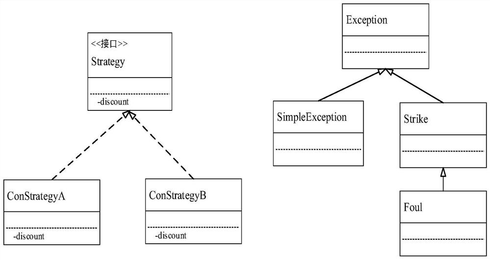
[0080] The source code in Table 1 contains three classes and an interface, the ConstrateGya class, and the ConstrateGyb class implement the Strategy interface, the Calprice method in the Context class calls the Discount method of the Strategy interface.

[0081] Step two based on abstract syntax tree build class inheritance diagram, such as image 3 Looking:

[0082] The abstract syntax tree of the source program contains three type declaration nodes, corresponding image 3 Node name in the middle. Analytic Type Declaration The method of declaring information is available, you can get image 3 The method information included in the middle node. Further resolve the type inform...


PUM


Abstract

The present invention proposes a method for constructing a control flow graph of an object-oriented program, the method comprising the following steps: 1) constructing an abstract syntax tree according to the source code; 2) constructing a class inheritance relationship diagram based on the abstract syntax tree; 3) according to the statement position relationship as The method constructs a coarse-grained control flow subgraph, and then uses node dismantling and virtual Finally node methods to construct a fine-grained control flow subgraph; 4) Uses the method of exception floating to analyze the control of exception throwing points and nested exception handling structures 5) Analyzing method call information, constructing a statement-based control flow graph; 6) Merging statement sets that do not cause changes in program execution order to form basic modules, and constructing a basic module-based control flow graph. The construction method of the invention not only supports the analysis of the influence of the polymorphic feature on the control flow, but also supports the control flow analysis of the multi-layer nested exception handling structure.

Description

Technical field [0001] The present invention relates to a control flow diagram structure for an object-oriented program, belonging to the technical field of program static analysis. Background technique [0002] The control flow diagram is an abstract manifestation of a process or program that represents all the paths traversed in a program execution. For a process or program P, typically represented a control flow diagram of P using a quadritical group G = (N, E, ENTRY, EXIT). Where n is a collection of nodes. This node contains two basic modules and simple statements. The former refers to the set of statements that do not cause the program execution order, the latter is to see each simple statement as a control flow node; E is Side set, each side is an ordered node pair <ni, nj>, which represents control transfer from Ni to NJ (ie, execute nj immediately after the statement Ni is executed); Entry and EXIT represent the subroutine The entrance and exit node. Control flow a...

Claims


Application Information

Patent Timeline
Patent Type & Authority Patents(China)
IPC IPC(8): G06F8/20
CPCG06F8/20
Inventor 李必信朱玲媛
Owner SOUTHEAST UNIV
Why Eureka
Try Eureka