Backlight module and display device with same

A technology of backlight module and fluorescent film, applied in the field of backlight module and display device, can solve the problems of hollow gap change, loose diaphragm, unfavorable cost, etc., to increase transmittance, reduce the number of layers, and increase the light mixing distance Effect

Inactive Publication Date: 2019-03-01
WUHAN CHINA STAR OPTOELECTRONICS TECH CO LTD
View PDF5 Cites 10 Cited by
  • Summary
  • Abstract
  • Description
  • Claims
  • Application Information

AI Technical Summary

Problems solved by technology

However, the existence of the light mixing distance brings great challenges to the actual mass production of Mini-LED backlights, which will result in a low yield rate, which is not conducive to its cost reduction.
In detail, such as figure 2 as shown, figure 2 for adoption figure 1 Cross-sectional view of the backlight module with mixed light mode, from figure 2 It can be seen from the figure that the backlight module 9 cannot be added figure 1 The structure of the raised column 91 shown in the figure results in a hollow gap between the surface light source 94 and the diffusion sheet 90, but the diffusion sheet 90 loosens or falls off due to factors such as gravity or vibration, resulting in a change in the hollow gap, resulting in the confusion of the mini LED. uneven light
Therefore, for the light mixing method using a single diffusion sheet 90 and reserving a certain light mixing distance, in the process of assembling the backlight module 9, due to the limitation of the frame glue 8, mass production cannot be achieved, and there is a large reliability problem. risk, and the light mixing method using multiple diffusers will reduce the light efficiency of Mini-LED

Method used


Image

  • Backlight module and display device with same
  • Backlight module and display device with same
  • Backlight module and display device with same

Examples


Embodiment Construction

[0039] The following description of the embodiments refers to the accompanying drawings to illustrate specific embodiments in which the invention may be practiced. The directional terms mentioned in the present invention, such as "up", "down", "front", "back", "left", "right", "top", "bottom", etc., are only for reference to the attached drawings. direction. Therefore, the directional terms used are used to illustrate and understand the present invention, but not to limit the present invention.

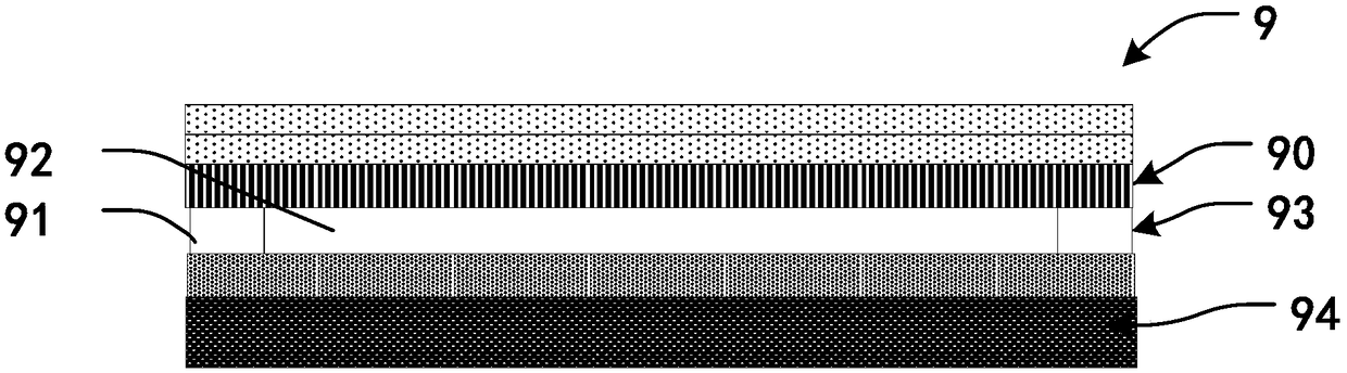
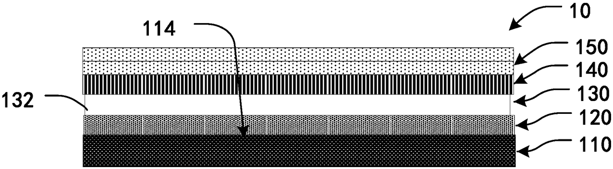
[0040] Such as image 3 As shown, in one embodiment, the backlight module 10 of the present invention includes a surface light source 110 , a fluorescent film 120 , a supporting layer 130 , a diffusion sheet 140 and a prism sheet 150 .

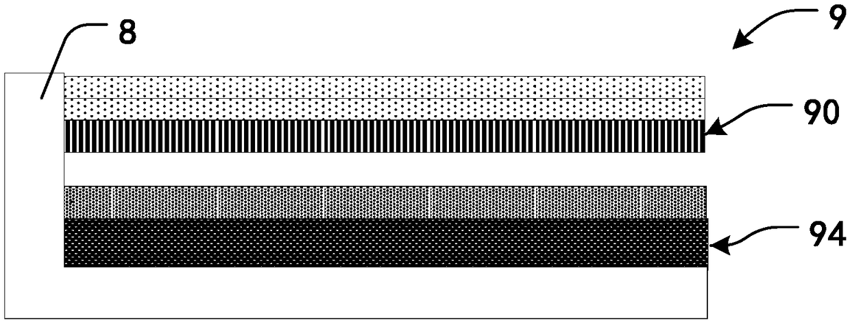
[0041] Such as Figure 4 As shown, the surface light source 110 has a light emitting surface 114 . In this embodiment, the surface light source 110 includes a substrate 111 , several chips 112 and a reflective layer 113 . One of the surfaces of t...


PUM


Abstract

The invention discloses a backlight module and a display device with the same. The backlight module includes a surface light source, a fluorescent film, a supporting layer and a diffusion sheet, wherein the surface light source is provided with a light emitting surface, the light-emitting surface of the surface light source is coated with the fluorescent film, the supporting layer is arranged on the fluorescent film, and the supporting layer is a transparent adhesive film layer; and the supporting layer is coated with the diffusion sheet. According to the backlight module and the display device with the same, under premise of ensuring higher lighting effect, the number of layers of the diffusion sheet in the backlight module is reduced, the transmittance of light is increased, thus a better light mixing effect and an efficient light-emitting effect are realized, and the purposes of uniform light mixing and thinning of the backlight module are achieved.

Description

technical field [0001] The invention relates to the field of displays, in particular to a backlight module and a display device with the backlight module. Background technique [0002] Mini-LED, also known as "submillimeter light-emitting diode", refers to LEDs with a grain size of about 100 microns. Mini-LED has attracted widespread attention from many manufacturers due to its many advantages such as high brightness, flexibility, low power consumption, thinness, and the ability to make narrow-frame samples. [0003] When assembling the backlight module of Mini-LED, it is necessary to meet the characteristics of uniform light mixing and as high as possible light efficiency. The uniformity of light mixing requires that Mini-LEDs have a certain light mixing distance when using a single diffuser; or use multiple diffusers to overlap each other for light mixing. Such as figure 1 As shown, when the existing backlight module 9 uses a single diffuser sheet 90 , it utilizes the p...

Claims


Application Information

Patent Timeline
Patent Type & Authority Applications(China)
IPC IPC(8): G09F9/30
CPCG09F9/30G02F1/133603G02F1/133612G02F1/133614G02F1/133605G02F1/133611G02F1/133606G02F1/133607G02B6/0031G02B6/4259
Inventor 杨勇查国伟
Owner WUHAN CHINA STAR OPTOELECTRONICS TECH CO LTD
Why Eureka
Try Eureka