
Battery cover plate of electronic equipment, preparation method thereof, and electronic equipment

A technology for electronic equipment and battery cover, which is applied to battery cover/end cover, branch equipment, battery pack components, etc., can solve the problems of battery cover to be improved, limited machinability, and inability to meet user requirements.

Active Publication Date: 2019-03-01
GUANGDONG OPPO MOBILE TELECOMM CORP LTD
View PDF7 Cites 6 Cited by
  • Summary
  • Abstract
  • Description
  • Claims
  • Application Information

AI Technical Summary

Problems solved by technology

[0002] The current plate battery cover plate usually uses glass fiber plate and plate bonding method. Not only is the preparation method more complicated, but also the incoming plate material is of uniform wall thickness, and the machinability is limited. After lamination, the numerical control lathe (CNC) only It can process a 2.5D arc with an edge width of about 1.6mm. As users have higher and higher requirements for the appearance and grip of electronic equipment, the current sheet battery cover is increasingly unable to meet the user's requirements
[0003] Therefore, the current plate battery cover still needs to be improved

Method used


Image

  • Battery cover plate of electronic equipment, preparation method thereof, and electronic equipment
  • Battery cover plate of electronic equipment, preparation method thereof, and electronic equipment
  • Battery cover plate of electronic equipment, preparation method thereof, and electronic equipment

Examples


Embodiment Construction

[0017] Embodiments of the present invention are described in detail below. The embodiments described below are exemplary only for explaining the present invention and should not be construed as limiting the present invention. If no specific technique or condition is indicated in the examples, it shall be carried out according to the technique or condition described in the literature in this field or according to the product specification. The reagents or instruments used were not indicated by the manufacturer, and they were all commercially available conventional products.

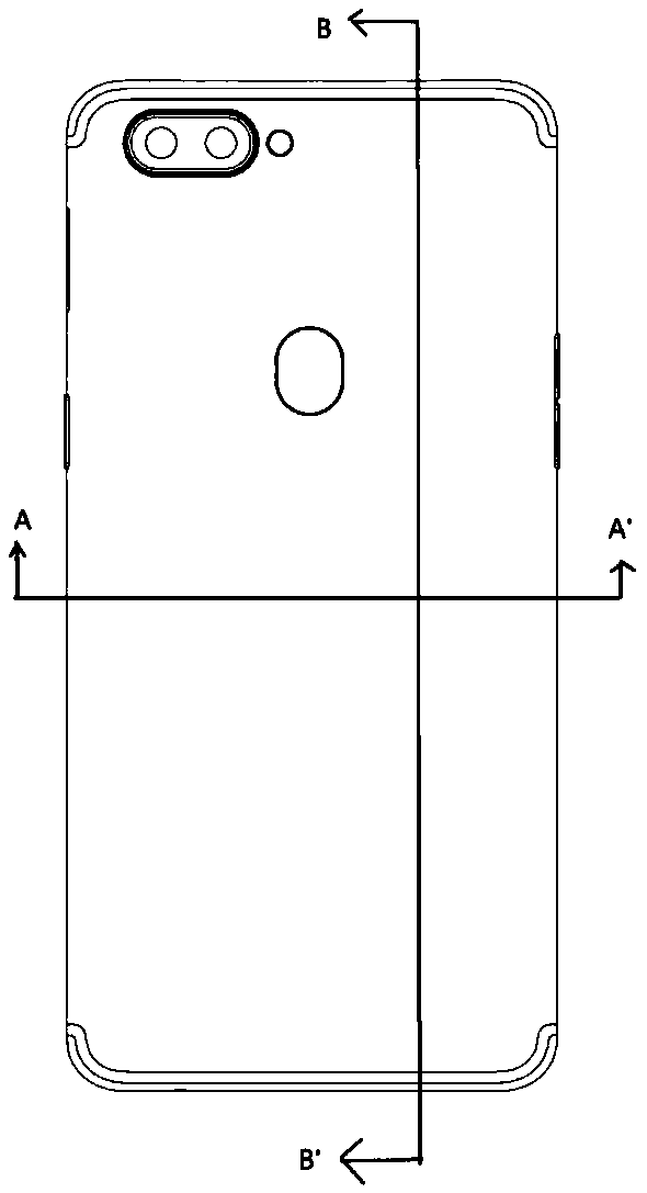
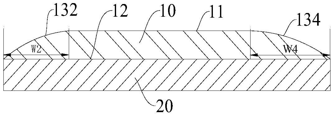
[0018] In one aspect of the present invention, the present invention provides a battery cover of an electronic device. According to an embodiment of the present invention, refer to figure 1 , figure 2 and image 3 , the electronic device battery cover 100 includes: a transparent injection molded part 10, the transparent injection molded part 10 has a top wall 11, a bottom wall 12 and a side wall, the ...


PUM

PropertyMeasurementUnit
Thicknessaaaaaaaaaa

Abstract

The invention provides a battery cover plate of electronic equipment, a preparation method thereof, and the electronic equipment. The battery cover plate of the electronic equipment comprises a transparent injection molded part and a decorative membrane, wherein the transparent injection molded part is provided with a top wall, a bottom wall and side walls; the side walls are located between and connected with the top wall and the bottom wall; the side walls include the front side wall, the left side wall, the rear side wall and the right side wall which are connected end to end; the left sidewall and the right side wall are of arc faces and protrude away from each other; the widths of the orthographic projections of the left side wall and the right side wall on the bottom wall are independently 2-35 mm; and the decorative membrane is arranged on the outer surface of the bottom wall. The battery cover plate of the electronic equipment can achieve large radian of edges, and has superior glossiness and texture and superior grip hand feeling and visual experience of users compared with plate battery covers in the related art. In addition, the battery cover plate of the electronic equipment has the transparency close to that of glass, and solves the problems that a glass battery cover plate is fragile, difficult to process, high in cost and low in yield.

Description

technical field [0001] The invention relates to the technical field of electronic equipment, and in particular, relates to a battery cover plate of an electronic equipment, a preparation method thereof, and an electronic equipment. Background technique [0002] The current plate battery cover plate usually uses the method of laminating glass fiber plate and plate. Not only is the preparation method more complicated, but also the incoming plate material is of uniform wall thickness, and the machinability is limited. After lamination, the numerical control lathe (CNC) only It can process a 2.5D arc with an edge width of about 1.6mm. As users have higher and higher requirements for the appearance and grip of electronic equipment, the current sheet battery cover is increasingly unable to meet the user's requirements. [0003] Therefore, the current plate battery cover still needs to be improved. Contents of the invention [0004] The present invention aims to solve one of the...

Claims


Application Information

Patent Timeline
IPC IPC(8): H01M2/04B29D7/00H04M1/02H01M50/147
CPCH04M1/0262B29D7/00H01M50/147Y02E60/10
Inventor 周小斌
Owner GUANGDONG OPPO MOBILE TELECOMM CORP LTD
Learn More