
Low-latency resolution adaptive video fiber transmission codec device

A technology of optical fiber transmission and resolution, which is applied in the direction of TV system adapting to optical transmission, video signal spatial resolution conversion, cable transmission adaptation, etc. It can solve the problems that the optical fiber receiving end cannot recognize the video and cannot adapt to the resolution, etc., to achieve The effect of low-latency resolution

Inactive Publication Date: 2019-03-01
CHINA AVIATION OPTICAL-ELECTRICAL TECH CO LTD
View PDF4 Cites 5 Cited by
  • Summary
  • Abstract
  • Description
  • Claims
  • Application Information

AI Technical Summary

Problems solved by technology

[0002] The traditional optical fiber transmission method of video is based on image restoration, and the transmission data is transmitted in one frame or one field. The video input terminal needs to buffer one frame or one field of video data, and then send out one frame or one field of video data. Video data; the video output end will also cache one frame or one field of video data, and then restore it; in the actual transmission process, both the video input and output ends need to wait for one frame or one field of video data, so there will be a relatively long Large delay, this delay time will be related to the video display refresh rate and video data processing, usually greater than 40ms; when switching videos with different resolutions, the video data will also change accordingly, and the display timing will also change accordingly , the optical fiber receiving end cannot recognize videos with different resolutions and different frame rates and field frequencies, resulting in the problem of not being able to adapt to the resolution

Method used


Image

  • Low-latency resolution adaptive video fiber transmission codec device
  • Low-latency resolution adaptive video fiber transmission codec device

Examples


Embodiment Construction

[0015] The present invention can be explained in more detail by the following examples, and the purpose of disclosing the present invention is intended to protect all changes and improvements within the scope of the present invention, and the present invention is not limited to the following examples: a low time-delay resolution automatic A codec device adapted to video optical fiber transmission, including a video input terminal and a video output terminal;

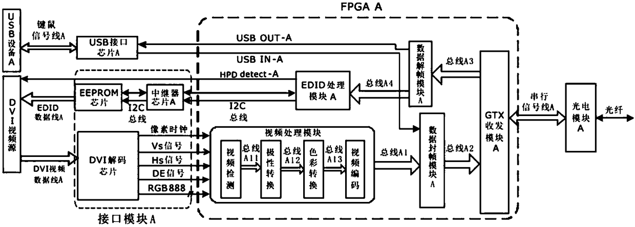
[0016]Wherein the video input end comprises DVI video source, USB equipment A, FPGA A, interface module A, USB interface chip A, photoelectric module A; Described FPGA A is a programmable logic device, generates video processing module, Data framing module A, data deframing module A, EDID processing module A; the FPGA A is also integrated with a GTX transceiver module A; the video processing module is connected to the data framing module A through a one-way transmission bus A1, and the data Frame sealing module A and GTX...


PUM


Abstract

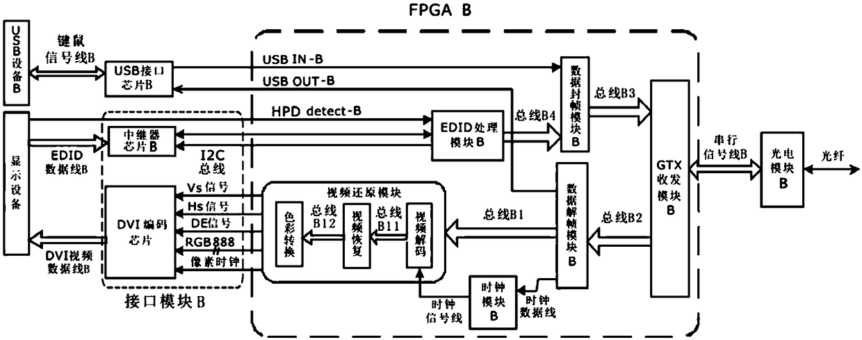
A low-latency resolution adaptive video fiber transmission codec device comprises a video input end and a video output end, wherein the video input end comprises USB equipment A, an FPGA A, an interface module A, a USB interface chip A, and a photoelectric module A; the video output end comprises a photoelectric module B, an FPGA B, an interface module B, a USB interface chip B, and USB equipmentB; the FPGA A programs to generate a video processing module, a data frame closing module A, a data de-framing module A, and an EDID processing module A; the FPGA B programs to generate a data de-framing module B, a data frame closing module B, a clock module B, a video restoration module, and an EDID processing module B; the video input end obtains video data and control timing by real-time synchronous waveform sampling of the FPGA A, and re-encodes the video data and control timing to enable synchronous transmission of video encoding and timing encoding; and the video output end performs video synchronous restoration on the received video encoding and timing encoding through the FPGA B to achieve the purpose of low delay and resolution adaptation.

Description

technical field [0001] The invention relates to the technical field of optical fiber transmission of video signals, in particular to a low-latency display resolution adaptive video optical fiber transmission encoding and decoding device for high-definition video single optical fiber transmission. Background technique [0002] The traditional optical fiber transmission method of video is based on image restoration, and the transmission data is transmitted in one frame or one field. The video input terminal needs to buffer one frame or one field of video data, and then send out one frame or one field of video data. Video data; the video output end will also cache one frame or one field of video data, and then restore it; in the actual transmission process, both the video input and output ends need to wait for one frame or one field of video data, so there will be a relatively long Large delay, this delay time will be related to the video display refresh rate and video data pro...

Claims


Application Information

Patent Timeline
IPC IPC(8): H04N7/22H04N7/01H04N5/06H04N5/765
CPCH04N5/06H04N5/765H04N7/0117H04N7/22
Inventor 李跃文王永星左朋莎王智辉陈旭辉郭子昂
Owner CHINA AVIATION OPTICAL-ELECTRICAL TECH CO LTD
Learn More