
Heat dissipation plate and manufacturing method thereof

A manufacturing method and technology for a heat dissipation plate, which are applied in cooling/ventilation/heating transformation, electrical equipment structural parts, instruments, etc., can solve the problems of complex heat pipe structure, increased manufacturing cost of electronic products, and unfavorable thin design of electronic products.

Active Publication Date: 2019-03-01
AVARY HLDG (SHENZHEN) CO LTD +1
View PDF6 Cites 0 Cited by
  • Summary
  • Abstract
  • Description
  • Claims
  • Application Information

AI Technical Summary

Problems solved by technology

However, the complex internal structure of heat pipes usually increases the manufacturing cost of electronic products
On the other hand, electronic products equipped with heat pipes need to reserve a certain space to accommodate the heat pipes, which is not conducive to the thin and light design of electronic products

Method used


Image

  • Heat dissipation plate and manufacturing method thereof
  • Heat dissipation plate and manufacturing method thereof
  • Heat dissipation plate and manufacturing method thereof

Examples


Embodiment 1

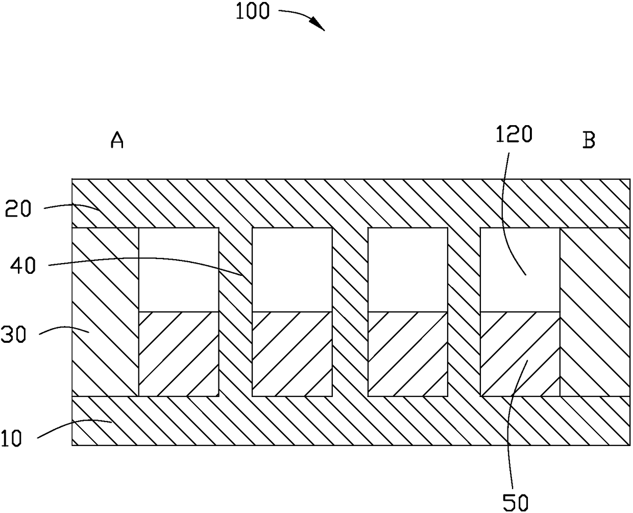
[0038] like figure 1 As shown, in the embodiment of the present invention, the heat dissipation plate 100 is used for dissipating heat in an electronic product.

[0039] The heat dissipation plate 100 includes a first plate body 10 , a second plate body 20 disposed opposite to the first plate body 10 , a fixing adhesive layer 30 connecting the first plate body 10 and the second plate body 20 , a support column 40 , and the cooling liquid 50 accommodated between the first plate body 10 and the first plate body 10 .

[0040] The heat dissipation plate 100 has a first end A and a second end B. The first section A is an evaporation section, and the second end B is a condensation section.

[0041] Understandably, the first section A is the condensation end, and the second end B is the evaporation end. The first end A and the second end B are located at two ends of the first plate body 10 respectively.

[0042] In the heat dissipation plate 100 according to the first embodiment ...

no. 2 example

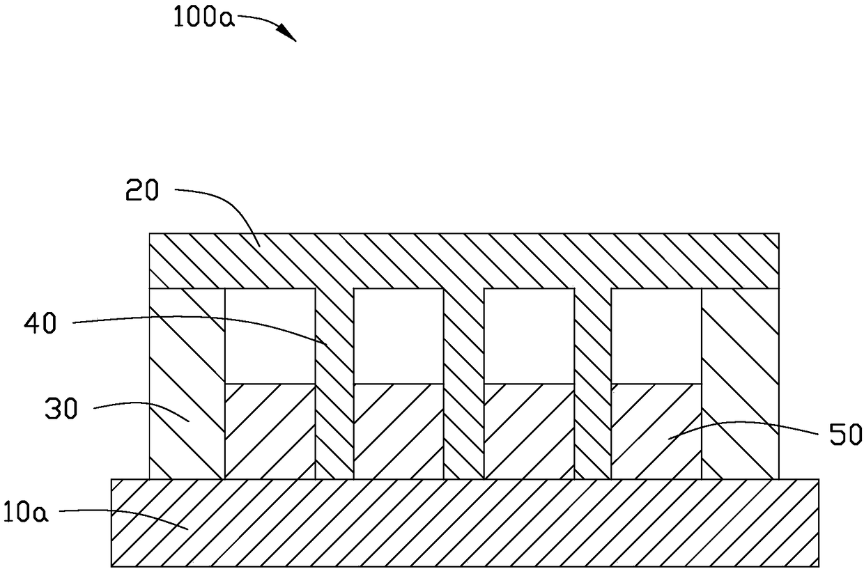
[0053] like figure 2 As shown, the heat dissipation plate 100a of the second embodiment of the present invention is similar to the heat dissipation plate 100 of the first embodiment, and the difference is that the first plate body 10a is an electronic product support structure.

no. 3 example

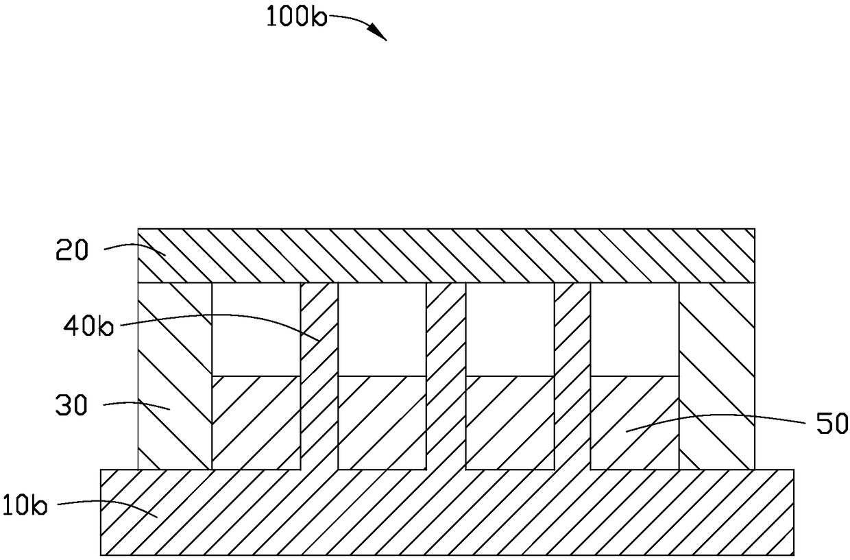
[0055] like image 3As shown, the heat dissipation plate 100b of the third embodiment of the present invention is similar to the heat dissipation plate 100 of the first embodiment, and the difference lies in that: the first plate body 10b is a supporting structure for electronic products, and the support columns 40b are Electronic product support structure. The support column 40b and the first plate body 10b are separately formed or integrally formed. The support column 40b extends vertically from the first plate body 10b toward the first plate body 10b and is connected to the second plate body 20 .

[0056] like Figure 4 As shown, when the heat dissipation plate of the present invention works, the first end A of the heat dissipation plate is in contact with a heat source 200 . The cold cooling liquid 50 is evaporated at the first end A, and the evaporated gas of the cooling liquid 50 flows back to the second end B along the inner wall of the first plate body 10 after bein...


PUM

PropertyMeasurementUnit
Surface tensionaaaaaaaaaa
Tensionaaaaaaaaaa

Abstract

The invention discloses a heat dissipation plate matched with an electronic product for heat dissipation. The heat dissipation plate comprises a first plate body, a second plate body, fixed glue layers connected to two ends of the first plate body and two ends of the second plate body, at least one support pillar and cooling liquid, wherein the first plate body, the second plate body and the fixedglue layers are encircled together to form a sealed cavity; the cooling liquid is accommodated in the cavity; the at least one support pillar is positioned inside the cavity; the support pillar is vertical to the first plate body and the second plate body; the cavity is connected with the at least one support pillar; the evaporation heat of the cooling liquid is 112 kj / kg to 119 kj / kg; the specific heat of the cooling liquid is 1183 J / kg.K to 1220 J / kg.K; the second plate body is made of copper, and is used for connecting with a heat source of the electronic product; and the surfaces, facingthe cavity, of the first plate body and the second plate body are surfaces without capillary structure.

Description

technical field [0001] The invention relates to a heat dissipation plate, in particular to a heat dissipation plate and a manufacturing method thereof. Background technique [0002] Today's electronic products, such as mobile phones, tablets, smart bracelets, etc., are developing rapidly. Electronic products have more functions and stronger performance, so as to better meet the needs of consumers and improve the effect of consumer experience. [0003] The stronger performance of these electronic products needs to be realized by increasing the data processing speed, so that the electronic products need to be configured with high-frequency, multi-core CPUs and highly integrated circuits. However, the higher the frequency of the CPU, the higher the number of cores, and the higher the integration of the circuit board, the more heat is generated, and the electronic products need to be equipped with better heat dissipation methods to ensure normal operation. [0004] At present, ...

Claims


Application Information

Patent Timeline
IPC IPC(8): H05K7/20
CPCH05K7/2029H05K7/20336H01L23/427G06F1/203G06F2200/201H01L23/473
Inventor 胡先钦沈芾云何明展徐筱婷
Owner AVARY HLDG (SHENZHEN) CO LTD
Features
  • Generate Ideas
  • Intellectual Property
  • Life Sciences
  • Materials
  • Tech Scout
  • Unparalleled Data Quality
  • Higher Quality Content
  • 60% Fewer Hallucinations
Learn More