Valve for closing and opening a line system

A technology for piping systems, closing elements, applied in the direction of devices used to relieve pressure on sealing surfaces, valve details, valve devices, etc., can solve problems such as increased current consumption, negative effects of fuel consumption, reduced effective distance, etc., Achieving the effect of low additional cost

Active Publication Date: 2019-03-01
KENDRION VILLINGEN GMBH
View PDF5 Cites 0 Cited by
  • Summary
  • Abstract
  • Description
  • Claims
  • Application Information

AI Technical Summary

Problems solved by technology

In addition, the current consumption that occurs with the activation of the solenoid valve has a significant negative impact on the fuel consumption of the relevant vehicles running with internal combustion engines
In the case of electric vehicles, the effective range is reduced due to the increased current consumption

Method used


Image

  • Valve for closing and opening a line system
  • Valve for closing and opening a line system
  • Valve for closing and opening a line system

Examples


Embodiment Construction

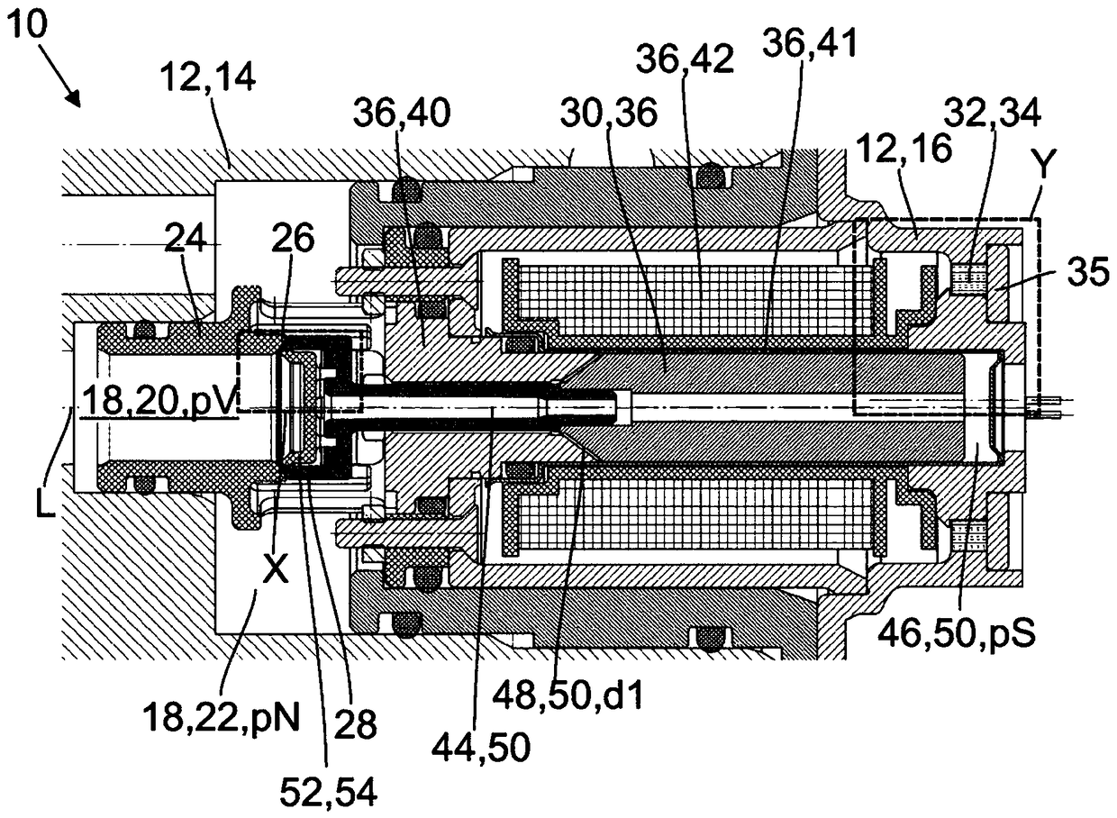
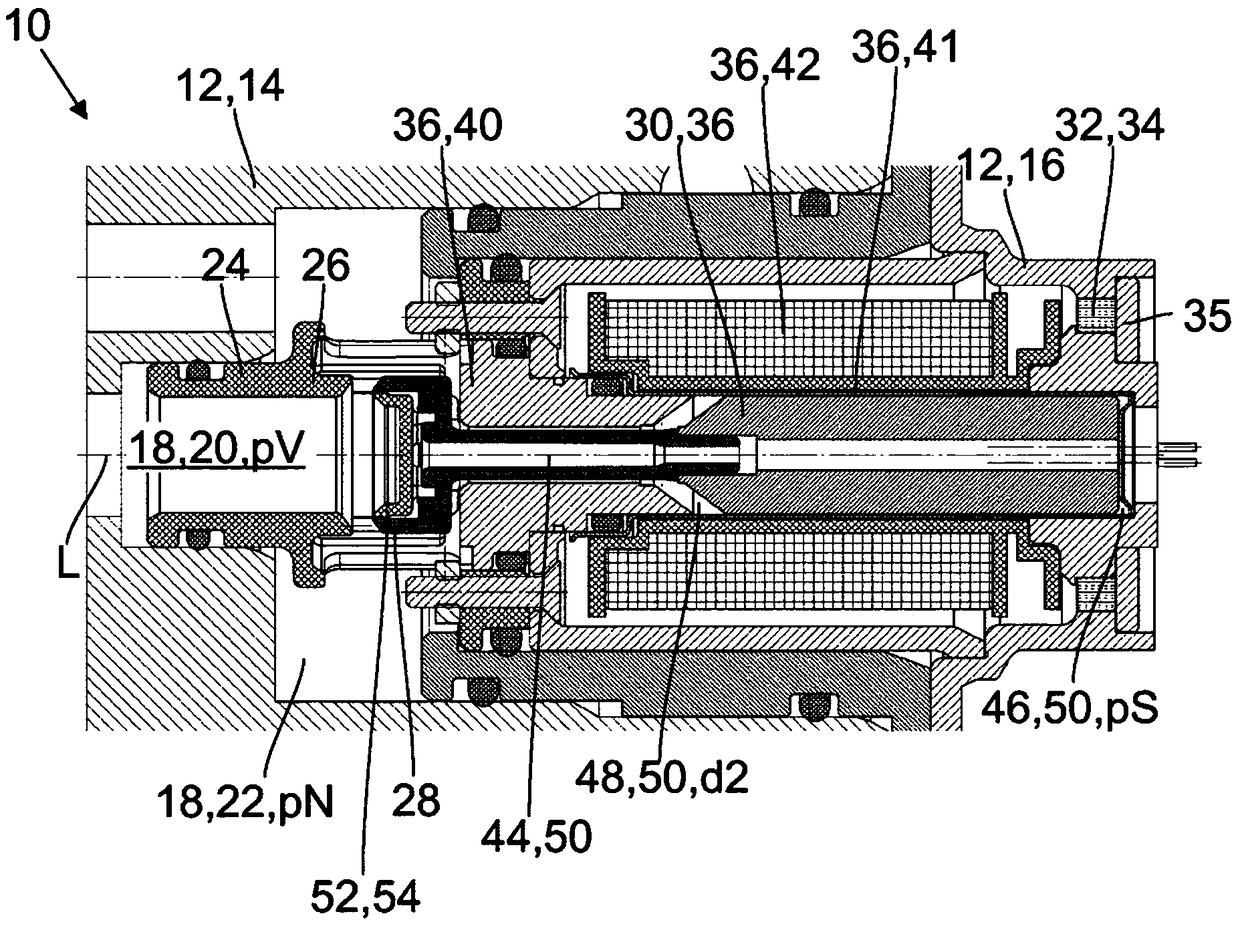
[0042] exist figure 1 An embodiment of a fluid control valve 10 according to the invention is shown in cross-section in FIG. The valve 10 has a housing 12 with a first housing part 14 and a second housing part 16, wherein a line system 18 is arranged in the first housing part 14, the line system 18 comprising an inlet line 20 and outlet pipeline 22. Furthermore, a valve body 24 which forms a valve seat 26 is arranged in the first housing part 14 . The valve body 24 can be made of metal or plastic, for example. Furthermore, the valve 10 comprises a closing element 28 which is arranged movably along the longitudinal axis L. As shown in FIG. The closing element 28 is connected to an armature 30 which cooperates with a reset element 32 , in this case with a radially magnetized permanent magnet 34 . The permanent magnet 34 is arranged in a correspondingly designed receptacle of the second housing part 16 and is fixed in this receptacle by means of a non-magnetic plate-shaped bo...


PUM


Abstract

The invention relates to a valve for closing and opening a line system, comprising a valve body (24) which is made of metal or plastic and forms a valve seat (26); a line system (18) with a supply line (20) for supplying a fluid to the valve seat (26) and with a discharge line (22) for discharging the fluid from the valve seat (26), the fluid being under a supply pressure (pV) in the supply line (20) and under a working pressure (pN) in the discharge line (22); a closing element (28) which interacts with the valve seat (26) for closing and opening the line system, said closing element (28) releasing a throttle cross-section (A) between the valve seat (26) and the closing element (28); a restoring element (32) which applies a restoring force to the closing element (28), the restoring forcepressing the closing element (28) against the valve seat (26) in order to close the line system; and a pressure chamber (46), in which the fluid is under a closing pressure (pS), with which the fluidapplies a closing force to the closing element (28) in order to close the line system (18). The valve (10) has means (52), by which the closing pressure (pS) in the pressure chamber (46) can be reduced below the supply pressure (pV) as a function of the released throttle cross-section (A). The invention further relates to a vehicle comprising such a valve and to a method for operating such a valve.

Description

technical field [0001] The invention relates to a valve for closing and opening pipeline systems. Background technique [0002] Valves generally have a fixed seat with which the piping system can be closed and opened such that a movable closing element cooperates with the seat. This pipeline system comprises an inlet pipeline for introducing fluid to the valve seat and an outlet pipeline for outlet fluid from the valve seat, wherein the fluid is under supply pressure in the inlet pipeline and is at work in the outlet pipeline under pressure. Some applications require that the valve close as long as the supply pressure is below a certain threshold and open once the supply pressure exceeds the threshold. [0003] In principle, this characteristic can be realized by means of an adjusting device, which moves the closing element accordingly when a threshold value is exceeded or undershot. For example, solenoid valves can be used for this. However, a pressure sensor must be pr...

Claims


Application Information

Patent Timeline
Patent Type & Authority Applications(China)
IPC IPC(8): F16K31/383
CPCF16K31/383F16K39/02Y10T137/7761Y10T137/7764Y10T137/7765Y10T137/7766Y10T137/7771
Inventor 马丁·奥马赫特沃尔弗拉姆·麦沃尔德沃尔夫冈·伯克斯特凡·巴思
Owner KENDRION VILLINGEN GMBH
Why Eureka
Try Eureka