Exhaust gas emission and treatment equipment

A treatment equipment and waste gas emission technology, which is applied to the separation of dispersed particles, chemical instruments and methods, and the use of liquid separating agents. Issues such as limited contact surface area

Inactive Publication Date: 2019-03-05
苏进邦 +2
View PDF8 Cites 0 Cited by
  • Summary
  • Abstract
  • Description
  • Claims
  • Application Information

AI Technical Summary

Problems solved by technology

For example, through the scrubber, etc., after the waste gas is splashed and soaked by the water of the scrubber, the suspended particles in the waste gas will be settled, and even the screen plate that makes the exhaust gas pass through the filter can strengthen the water splashing and leaching effect of the aforementioned scr...

Method used


Image

  • Exhaust gas emission and treatment equipment
  • Exhaust gas emission and treatment equipment
  • Exhaust gas emission and treatment equipment

Examples


Embodiment Construction

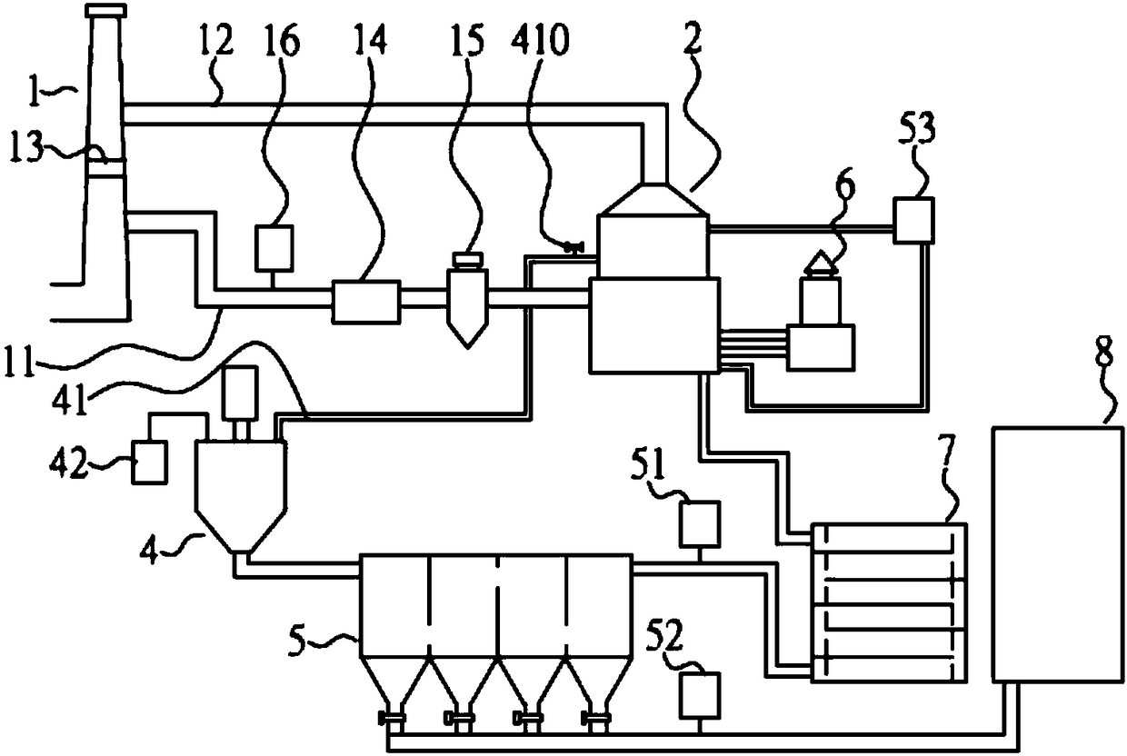
[0041] see figure 1 As shown, the present invention provides a waste gas emission treatment device, which includes a chimney pipe (1) connected to a washing unit (2) through an inlet pipe (11).

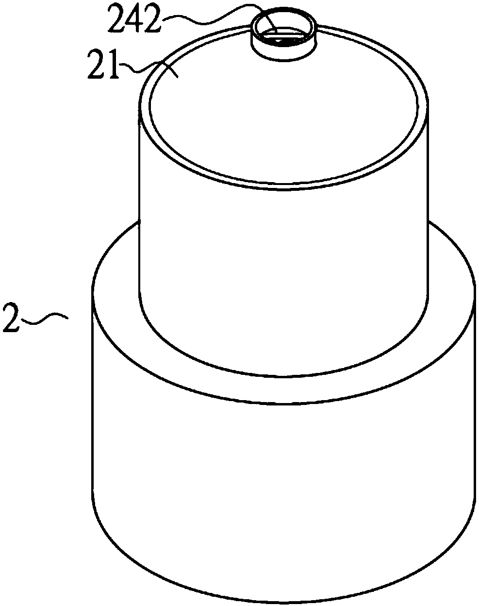
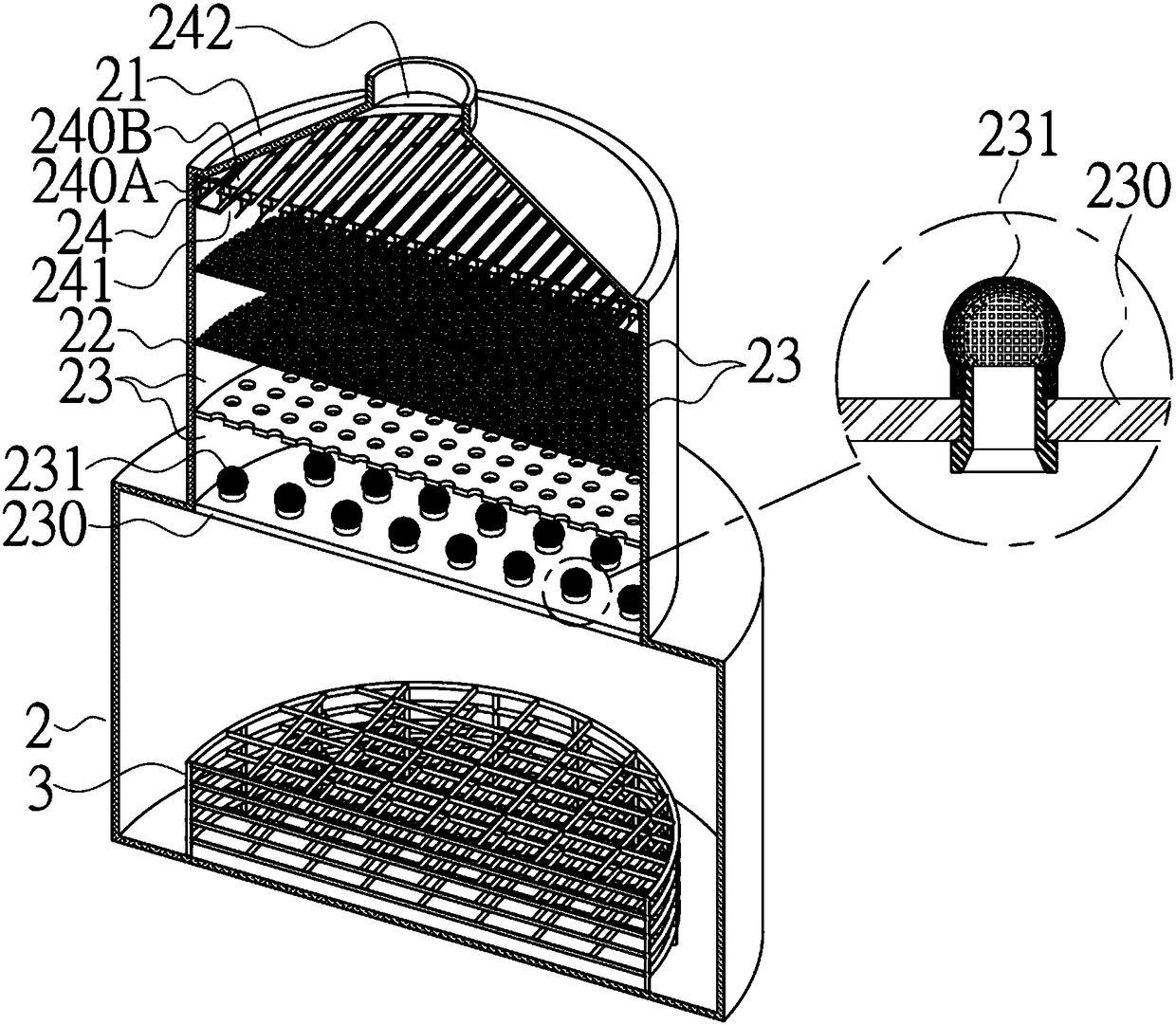
[0042] like figure 2 and image 3 Shown, this washing unit (2) comprises a cover (21), frame encircles and limits a washing chamber (22), and this washing chamber (22) is provided with multi-layer grid dish (23) from top to bottom, and this washing In the chamber (22) for containing water (such as Figure 4 shown).

[0043] see figure 2 Shown, wherein one layer of net pan (23) of multi-layer net pan (23) is made up of a plurality of spherical screens (231) that are provided with on a plate body (230) and it, and each this Below the spherical mesh screen (231) and the washing chamber (22) communicate directly or indirectly with the inlet pipe (11), and the washing chamber (22) communicates with the chimney pipe (1) through an outlet pipe (12). In one embodiment of the present i...


PUM


Abstract

The present invention discloses an exhaust gas emission and treatment system comprising a chimney pipe connected to a washing unit through a feeding pipe. The main object of the present invention is to create more disturbance and larger contact area with water before exhaust gas reaches a discharging pipe in a limited cross-sectional area. For this object, one mesh disk of a plurality of layers ofmesh disks is composed of a plate body and a plurality of spherical mesh screens arranged thereon, so that when the exhaust gas passes through the mesh disk, a plurality of spherical mesh screens areformed in one layer and in a plurality of layers and exhaust gas is highly filtrated when the exhaust gas passes through the spherical mesh screens, so that the contact surface area with water when the exhaust gas passes is larger and more sufficient, the effect that exhaust gas is in contact with water during emission is better and exhaust emission is reduced.

Description

technical field [0001] The invention relates to waste gas treatment equipment, in particular to waste gas discharge treatment equipment. Background technique [0002] The problem of waste discharge often occurs during industrial production and manufacturing. The relatively light exhaust gas in the waste is usually discharged from a chimney pipe, and is usually burned or treated first or burned in the chimney pipe, and then discharged to the outside after treatment. . However, the issue of environmental protection has always been paid attention to, and the exhaust gas discharged from the chimney has always been tested and required by environmental protection. [0003] Although the exhaust gas entering the chimney may have undergone a considerable degree of pre-treatment, it is still unavoidable. There will still be soot, dust, odor components, suspended particles, etc. in the exhaust gas. , and different treatment methods may be adopted to meet emission standards. For exam...

Claims


Application Information

Patent Timeline
IPC IPC(8): B01D47/02B01D50/00
CPCB01D47/021B01D50/60
Inventor 苏进邦陈四福王美侦
Owner 苏进邦
Why Eureka
Try Eureka