Al technical title is built by PatSnap Al team. It summarizes the technical point description of the patent document.
A purging equipment and jet type technology, which is applied in the field of plane jet type subway tunnel purging equipment, can solve the problems of small air flow, small compressed air nozzle holes, increase the humidity of the tunnel, etc., and achieve the effect of high equipment efficiency.
Pending Publication Date: 2019-03-05
CHINA RAILWAY HUATIE ENG DESIGN GRP CO LTD
View PDF16 Cites 1 Cited by
Summary
Abstract
Description
Claims
Application Information
AI Technical Summary
This helps you quickly interpret patents by identifying the three key elements:
Problems solved by technology
Method used
Benefits of technology
Problems solved by technology
Since there are electrical equipment in the tunnel, high-pressure water washing can only clean the area below 1.4 meters in the subway tunnel, and the humidity in the tunnel increases after washing, which has a certain impact on the facilities in the tunnel, and there is also the problem of cleaning wastewater discharge
The compressed air purge air flow is a free jet with a circular cross-section, the compressed air nozzle hole is small, the air flow is small, and the purge air velocity decays quickly, so the blowing effect on the inner wall of the tunnel and various facilities far away from the compressed air nozzle is not ideal.
Method used
Image
Click on the blue label to locate the original text in one second.
Reading with bidirectional positioning of images and text.
Examples
Embodiment Construction
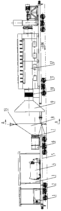
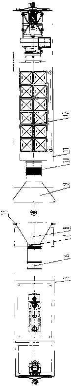
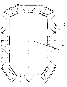
[0024] Attached below figure 1 , figure 2 , image 3 , Figure 4 , Figure 5 , Image 6 , an embodiment will be described.
[0025] The plane jet type subway tunnel purging equipment can only choose to clean the subway tunnel during the time period when the subway trains are out of service. Under the scheduling arrangement of the subway operating company, the railway diesel locomotive is quickly pulled from the parking place of the purging equipment to the subway tunnel that needs to be purged and cleaned, and the subway tunnel is purged and cleaned at a relatively low speed. The operation process is as follows: start the diesel generator set (4) to provide power for the control system (1), the axial flow fan assembly (6) and the dust removal device (12), and the control system (1) controls the axial flow fan according to the conditions in the tunnel The motor speed of the assembly (6) provides the proper wind speed for the purging and cleaning operation. The high-spee...
PUM
Abstract
The invention relates to a metro tunnel ash cleaning device, belonging to the technical field of environmental protection of urban metro tunnels. Under the dispatching arrangement of the metro operation company, the plane jet type metro tunnel blowing device is quickly pulled from the blowing device parking place to the metro tunnel which has blowing and ash cleaning needs by a railway diesel locomotive, and the blowing and ash cleaning operation is carried out on the metro tunnel at a relatively low running speed. The plane jet type metro tunnel blowing device is mainly characterized in thata blowing nozzle (13) is arranged at the periphery of a pressure stabilizing box (8) and is close to the boundary of the metro vehicle, and the dust on the inner wall of the metro tunnel and adhered to various facilities is blown in a plane jet mode. The outer edge of an air suction port (9) is close to the metro vehicle gauge, and sucks the plane jet air discharged from the blowing nozzle (13) into a dust removing device (12) together with the raised dust, so that the dust is filtered down and the clean air is returned to the metro tunnel.
Description
1. Technical field [0001] The invention relates to the technical field of environmental protection of urban subway tunnels, in particular to a plane jet type subway tunnel purging device. 2. Background technology [0002] There are many facilities installed in the subway tunnel, such as local telephone cables, control cables, professional signal cables, AP antennas, overhead ground wires, lighting, police leaky cables, communication signal brackets, communication signal cables, strong electric cable brackets, Power cables, maintenance socket boxes, signals, line signs, etc. There are a large number of grooves, gaps, pipes, wires, etc. between these facilities (see Image 6 ), and the various facilities vary in size, height and shape. During the operation of subway trains, some dust will be generated. These dusts will adhere to the surface of the facilities in the subway tunnel, the inner wall of the tunnel, and settle in the ground of the subway tunnel and the grooves and g...
Claims
Application Information
Patent Timeline
Application Date:The date an application was filed.
Publication Date:The date a patent or application was officially published.
First Publication Date:The earliest publication date of a patent with the same application number.
Issue Date:Publication date of the patent grant document.
PCT Entry Date:The Entry date of PCT National Phase.
Estimated Expiry Date:The statutory expiry date of a patent right according to the Patent Law, and it is the longest term of protection that the patent right can achieve without the termination of the patent right due to other reasons(Term extension factor has been taken into account ).
Invalid Date:Actual expiry date is based on effective date or publication date of legal transaction data of invalid patent.