Tail gas treatment device and method

A technology for exhaust gas treatment and exhaust gas, which is applied in the direction of electronic control, exhaust gas treatment, and exhaust device of exhaust gas treatment devices, and can solve problems such as inability to filter exhaust gas, labor consumption, and environmental pollution.

Active Publication Date: 2019-03-05
陈爱国
View PDF7 Cites 0 Cited by
  • Summary
  • Abstract
  • Description
  • Claims
  • Application Information

AI Technical Summary

Problems solved by technology

[0005] The embodiment of the present invention provides a tail gas treatment device and method, which are used to solve the problems of manpower consumption a

Method used


Image

  • Tail gas treatment device and method
  • Tail gas treatment device and method
  • Tail gas treatment device and method

Examples


Embodiment Construction

[0031] The following will clearly and completely describe the technical solutions in the embodiments of the present invention with reference to the accompanying drawings in the embodiments of the present invention. Obviously, the described embodiments are only some, not all, embodiments of the present invention. Based on the embodiments of the present invention, all other embodiments obtained by persons of ordinary skill in the art without making creative efforts belong to the protection scope of the present invention.

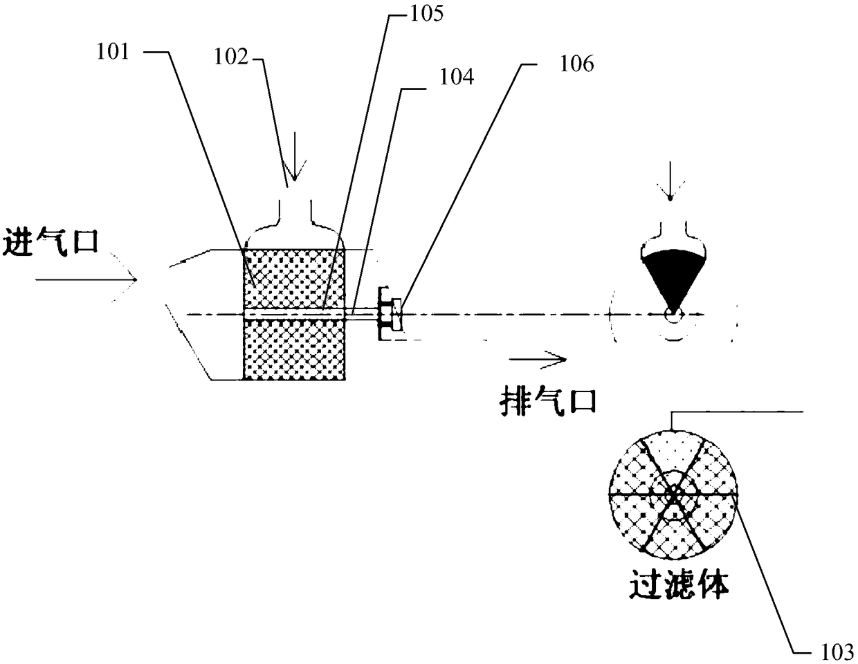
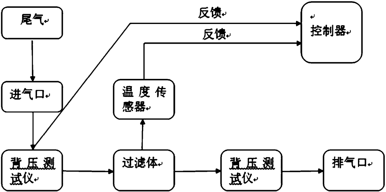
[0032] figure 1 A schematic structural diagram of an exhaust gas treatment device provided in an embodiment of the present invention, as shown in figure 1 As shown, the tail gas treatment device mainly includes a microwave heating regeneration system and a monitoring and control system.

[0033] Specifically, such as figure 1 As shown, the microwave heating regeneration system is set in the exhaust device, and the exhaust gas particles enter the microwave he...


PUM


Abstract

The invention discloses a tail gas treatment device and method, and relates to the technical field of tail gas treatment. The problem that cleaning and filtering cannot be carried out at the same timeduring existing tail gas treatment is solved. The device comprises a filter body and a micro wave emitter; the filter body comprises at least two areas, the first area is used for filtering tail gas,and the micro wave emitter is arranged above the filter body and is used for heating the second area of the filter body.

Description

technical field [0001] The invention relates to the technical field of tail gas treatment, in particular to a tail gas treatment device and method. Background technique [0002] In ships, the emission of particulate matter (English: Particulate Matter, PM for short) in ship exhaust is very high, which is very harmful to the environment. [0003] DPF (English: Diesel Particulate Filter) is a ceramic filter installed in the diesel engine exhaust system, which can capture particulate emissions before they enter the atmosphere. Working principle: For example, the diesel particulate filter is sprayed with metal platinum, rhodium, and palladium, and the black smoke containing carbon particles discharged from the diesel engine enters the engine exhaust particulate filter through a special pipe, and passes through the densely arranged bag filter inside it. , adsorb the soot particles on the filter made of metal fiber felt; when the adsorption amount of the particles reaches a certa...

Claims


Application Information

Patent Timeline
IPC IPC(8): F01N3/022F01N3/028F01N9/00
CPCF01N3/022F01N3/028F01N9/002Y02T10/40
Inventor 陈爱国唐伟炜陈景昱李军陈振豪吴丽华刘洋曹雪玲苏一丹黄赞
Owner 陈爱国
Why Eureka
Try Eureka