Wavelength Conversion Device and Laser Fluorescence Conversion Type Light Source

A wavelength conversion device and fluorescence technology, applied in the field of laser fluorescence conversion light source, can solve the problems of limitation and reduce product reliability, and achieve the effects of reducing light loss, improving lumen density, and good shock resistance

Active Publication Date: 2020-10-16
APPOTRONICS CORP LTD
View PDF13 Cites 0 Cited by
  • Summary
  • Abstract
  • Description
  • Claims
  • Application Information

AI Technical Summary

Problems solved by technology

However, due to the reliance of this technical solution on fluorescent wheels, its application in environments with frequent vibrations (such as vehicle equipment) is limited, and product reliability is also reduced.

Method used


Image

  • Wavelength Conversion Device and Laser Fluorescence Conversion Type Light Source
  • Wavelength Conversion Device and Laser Fluorescence Conversion Type Light Source
  • Wavelength Conversion Device and Laser Fluorescence Conversion Type Light Source

Examples


no. 1 example

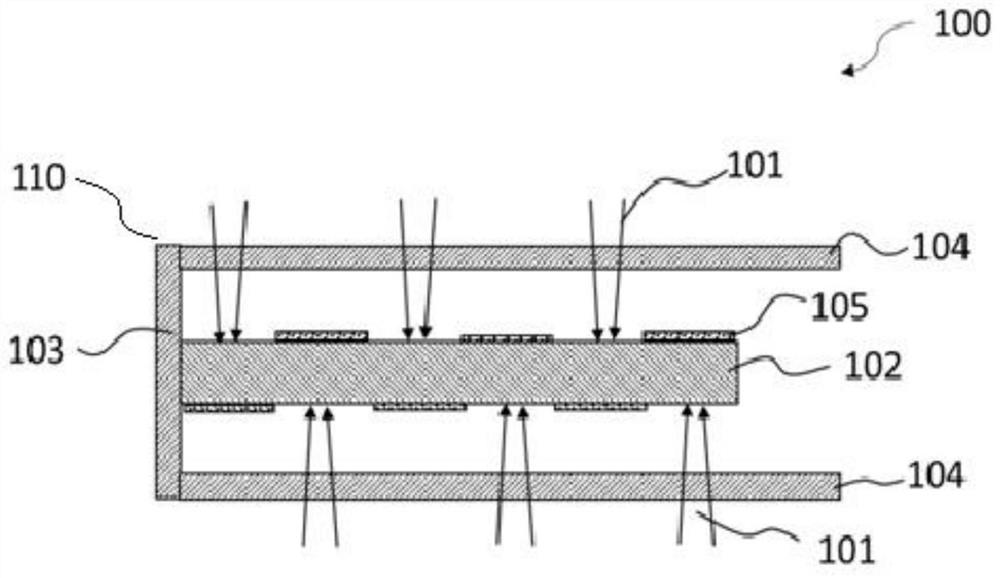
[0033]figure 1 A cross-sectional view of the wavelength conversion device 100 according to the first embodiment of the present invention is shown. The wavelength conversion device 100 includes an encapsulation housing 110 and a fluorescent component 102 . Such as figure 1 As shown, the packaging case 110 is formed as a cuboid with a cavity inside, including four side faces and a closed end face 103 . Here, will figure 1 The horizontal direction in is called the length direction of the package housing 110 and the fluorescent assembly 102, and the figure 1 The vertical direction in is called the thickness direction of the package housing 110 and the fluorescent assembly 102, and the figure 1 The direction perpendicular to the paper surface is called the width direction of the packaging case 110 and the fluorescent assembly 102 . Two opposite side surfaces (an upper surface and a lower surface in the figure) extending in the longitudinal direction of the package case 110 are ...

no. 2 example

[0044] Image 6 A wavelength conversion device 200 according to a second embodiment of the present invention is illustrated. The structure of the wavelength conversion device 200 is substantially the same as that of the wavelength conversion device 100 of the first embodiment. The wavelength conversion device 200 includes a package housing 210 and a fluorescent component 202 . The package case 210 is formed as a cuboid having a cavity inside. One end of the packaging case 210 is a closed end formed with a closed end surface 203 , and the other end is open. Incident light windows 204 are provided on two opposite surfaces of the packaging case 210 extending along the lengthwise direction. One end face of the fluorescent assembly 202 is firmly connected to the inner surface of the closed end face 203 of the packaging case 210 . A Lambertian reflective layer 205 is disposed on the upper surface and the lower surface of the fluorescent component 202 . In the following descript...

no. 3 example

[0051] Figure 8 A wavelength conversion device 300 according to a third embodiment of the present invention is illustrated. The wavelength conversion device 300 includes an encapsulation case 310 and a fluorescent assembly 302 , and the encapsulation case 310 has a closed end face 303 . The wavelength conversion device 300 according to the third embodiment of the present invention is a modification of the wavelength conversion device 200 described above, and can be used in the case of incident multicolor laser light. In the following description, a description of components of the wavelength conversion device 300 substantially the same as those of the wavelength conversion device 200 will be omitted.

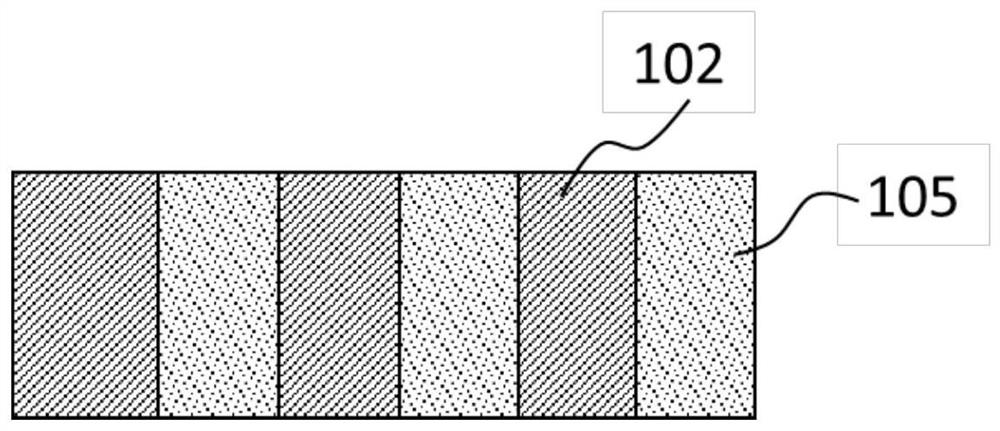
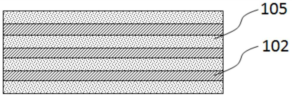
[0052] The biggest difference between the wavelength conversion device 300 and the wavelength conversion device 200 is that the fluorescent component 302 disposed in the packaging casing 310 has a multi-layer structure. Specifically, the multi-layer structure includes a first...


PUM

PropertyMeasurementUnit
thicknessaaaaaaaaaa
lengthaaaaaaaaaa
widthaaaaaaaaaa

Abstract

Provided are a wavelength conversion device (100), and a light source employing conversion of laser light to fluorescent light and having the device (100). The wavelength conversion device (100) comprises a sealed housing (110) and a fluorescent assembly (102). The fluorescent assembly (102) comprises a fluorescent material, and is configured for wavelength conversion. The sealed housing (110) is in the form of a rectangle and has four side surfaces and a sealing end surface (103). One end of the sealed housing (110) opposite to the sealing end surface (103) is an open emission end. Of the four side surfaces of the sealed housing, the two opposite side surfaces are light entering surfaces and form incident light windows (104). A surface of the incident light window (104) is provided with an optical film allowing passing of a specific light beam. Inner surfaces of the other two side surfaces and an inner surface of the sealing end surface (103) are specular reflective surfaces. The fluorescent assembly (102) is provided in a hollow cavity inside the sealed housing (110). The fluorescent assembly (102) is in the form of a sheet and one end thereof is connected to the sealing end surface (103). The light entering windows (104) face an upper surface and a lower surface of the fluorescent assembly (102). The upper surface and the lower surface of the fluorescent assembly (102) are respectively provided with at least one Lambertian reflection layer (105).

Description

technical field [0001] The present invention relates to a wavelength conversion device and a laser fluorescence conversion light source using the wavelength conversion device. Background technique [0002] In recent years, laser light source has become an important development direction of projection light source and illumination light source. At present, among numerous laser light source products, the mainstream technologies are mainly divided into two types, one is RGB three-color laser technology, and the other is laser phosphor technology. [0003] The three-color laser technology uses red, green and blue three-color laser modules. Its advantage is that the three-color components of R, G, and B can be adjusted independently, and the utilization rate of the laser light energy can reach 100%. However, in this technical solution, "speckle" defects are prone to appear in the projected picture, and human eyes are prone to damage eyes and vision when watching the picture with...

Claims


Application Information

Patent Timeline
Patent Type & Authority Patents(China)
IPC IPC(8): F21V9/40F21V7/04F21V9/00G03B21/20
CPCF21V7/04F21V9/00G03B21/204F21V9/40G03B21/20
Inventor 李乾陈雨叁许颜正
Owner APPOTRONICS CORP LTD
Why Eureka
Try Eureka