Wavelength Conversion Device and Laser Fluorescence Conversion Type Light Source

A wavelength conversion device and fluorescence technology, which is applied in the field of laser fluorescence conversion light source, can solve the problems of large heat generation, difficult application, low quantum efficiency of red phosphor powder, etc., achieve good shock resistance, improve light extraction efficiency, and reduce light loss Effect

Active Publication Date: 2020-12-15
APPOTRONICS CORP LTD
View PDF7 Cites 0 Cited by
  • Summary
  • Abstract
  • Description
  • Claims
  • Application Information

AI Technical Summary

Problems solved by technology

In addition, in this laser phosphor technology, compared with yellow phosphor and green phosphor, red phosphor has lower quantum efficiency and higher heat generation, so it is difficult to apply to higher power light source products

Method used


Image

  • Wavelength Conversion Device and Laser Fluorescence Conversion Type Light Source
  • Wavelength Conversion Device and Laser Fluorescence Conversion Type Light Source
  • Wavelength Conversion Device and Laser Fluorescence Conversion Type Light Source

Examples


no. 1 example

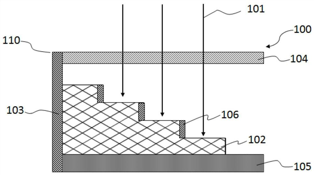
[0021] figure 1 A cross-sectional view of the wavelength conversion device 100 according to the first embodiment of the present invention is shown. The wavelength conversion device 100 includes a packaging component 110 and a fluorescent component 102 . Such as figure 1 As shown, the package assembly 110 is formed as a cuboid with a cavity inside, has four sides and a closed end surface 103 . Here, will figure 1 The horizontal direction in is called the length direction of the packaging component 110 and the fluorescent component 102, and the figure 1 The vertical direction in is called the thickness direction of the packaging component 110 and the fluorescent component 102, and the figure 1 The direction perpendicular to the paper surface in is referred to as the width direction of the packaging component 110 and the fluorescent component 102 . One of the four sides of the package assembly 110 ( figure 1 The upper surface in the middle) is used as a light incident end, ...

no. 2 example

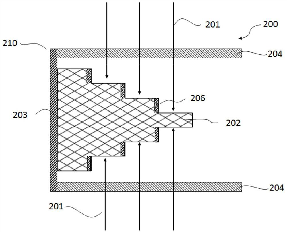
[0029] figure 2 A wavelength conversion device 200 according to a second embodiment of the present invention is illustrated. The wavelength conversion device 200 includes a package component 210 and a fluorescent component 202 , the package component 210 has a closed end face 203 . The wavelength conversion device 200 according to the second embodiment of the present invention is a modification of the above-mentioned wavelength conversion device 100, capable of receiving irradiation of opposite double-sided lasers. In the following description, a description of components of the wavelength conversion device 200 that are substantially the same as those of the wavelength conversion device 100 will be omitted.

[0030] The difference between the wavelength conversion device 200 and the wavelength conversion device 100 is that the two opposite sides of the packaging component 210 are respectively provided with incident light windows 204, the upper surface and the lower surface o...

no. 3 example

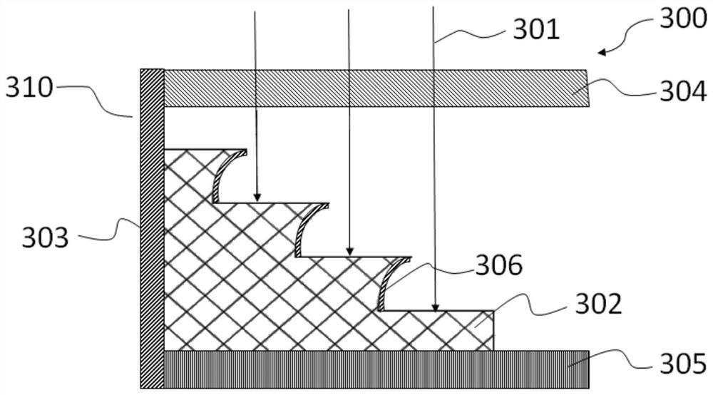
[0033] image 3 A wavelength conversion device 300 according to a third embodiment of the present invention is illustrated. The structure of the wavelength conversion device 300 is substantially the same as that of the wavelength conversion device 100 of the first embodiment. The wavelength conversion device 300 includes a packaging component 310 and a fluorescent component 302 . The package assembly 310 is formed as a cuboid having a cavity inside. The package assembly 310 has a closed end face 303, and an end opposite to the closed end face 303 is opened and serves as a light exit end. One surface ( image 3 The upper surface in the middle) is provided with an incident light window 304 . The surface of the fluorescent assembly 302 facing the incident light window 304 ( image 3 The middle is the upper surface) is formed into a stepped structure with multiple steps, the lower surface is bonded with a ceramic heat sink substrate 305, and one end surface of the fluorescent...


PUM

PropertyMeasurementUnit
thicknessaaaaaaaaaa
reflectanceaaaaaaaaaa

Abstract

Provided are a wavelength conversion device (100, 200, 300, 400), and a light source employing conversion of laser light to fluorescent light. The wavelength conversion device (100, 200, 300, 400) comprises a sealed assembly (110, 210, 310, 410) and a fluorescent assembly (102, 202, 302, 402) capable of converting an incident light beam (101, 201, 301, 401) into an emitted light beam. The sealed assembly (110, 210, 310, 410) is in the form of a rectangle and has four side surfaces and a sealing end surface (103, 203, 303, 403). One end of the sealed assembly opposite to the sealing end surface (103, 203, 303, 403) is open and serves as a light emission end. Of the four side surfaces, one side surface or two opposite side surfaces serve as a light entering end or ends and form an incident light window or windows (104, 204, 304, 404). A surface of the incident light window (104, 204, 304, 404) is provided with an optical film allowing passing of a specific light beam. Inner surfaces of the side surfaces other than the side surface serving as the light entering end, and an inner surface of the sealing end surface (103, 203, 303, 403), are reflective surfaces. The fluorescent assembly (102, 202, 302, 402) is provided inside the sealed assembly (110, 210, 310, 410), and one end thereof is connected to the sealing end surface (103, 203, 303, 403). A surface of the fluorescent assembly (102, 202, 302, 402) opposite to the incident light window (104, 204, 304, 404) over an air gap has a stepped structure having a thickness decreasing in a stepwise pattern from the sealing end surface (103, 203, 303, 403) to the light emission end. Side walls of at least a portion of steps of the stepped structure are provided with Lambertian reflection layers or specular reflection layers (106, 206, 306, 406).

Description

technical field [0001] The present invention relates to a wavelength conversion device and a laser fluorescence conversion light source using the wavelength conversion device. Background technique [0002] In recent years, laser light sources have become an important development direction of projection light sources. With this development, the application fields of laser light sources have become more extensive. Whether it is from miniature projection to engineering projection to movie projectors, or from the field of projection light sources to the field of lighting light sources, the application forms of laser light sources are gradually diversified. and modularization. Applications in these different fields have different requirements on the functions and characteristics of laser light sources, so different optimized designs for laser light sources are required. [0003] Among the current numerous laser light source products, the mainstream technical solutions are mainl...

Claims


Application Information

Patent Timeline
Patent Type & Authority Patents(China)
IPC IPC(8): G03B21/20
CPCF21V7/04F21V7/06F21V29/86G03B21/204F21V7/00F21V9/00
Inventor 李乾陈雨叁许颜正
Owner APPOTRONICS CORP LTD
Why Eureka
Try Eureka