Multi-system co-coupling method and device

A multi-mode and standard technology, applied in connection management, wireless communication, network data management, etc., achieves the effect of simple parameter configuration, saving resources such as IP resources and device memory, and reducing the number of couplings

Active Publication Date: 2019-03-05
ZTE CORP
View PDF8 Cites 0 Cited by
  • Summary
  • Abstract
  • Description
  • Claims
  • Application Information

AI Technical Summary

Problems solved by technology

[0003] The embodiment of the present invention provides a method and device for multi-mode co-coupling, which solves the problem that each mode of multi-mode equipment shares one coupling for signaling transmission and reception

Method used


Image

  • Multi-system co-coupling method and device
  • Multi-system co-coupling method and device
  • Multi-system co-coupling method and device

Examples


Embodiment Construction

[0038] The preferred embodiments of the present invention will be described in detail below in conjunction with the accompanying drawings. It should be understood that the preferred embodiments described below are only used to illustrate and explain the present invention, and are not intended to limit the present invention.

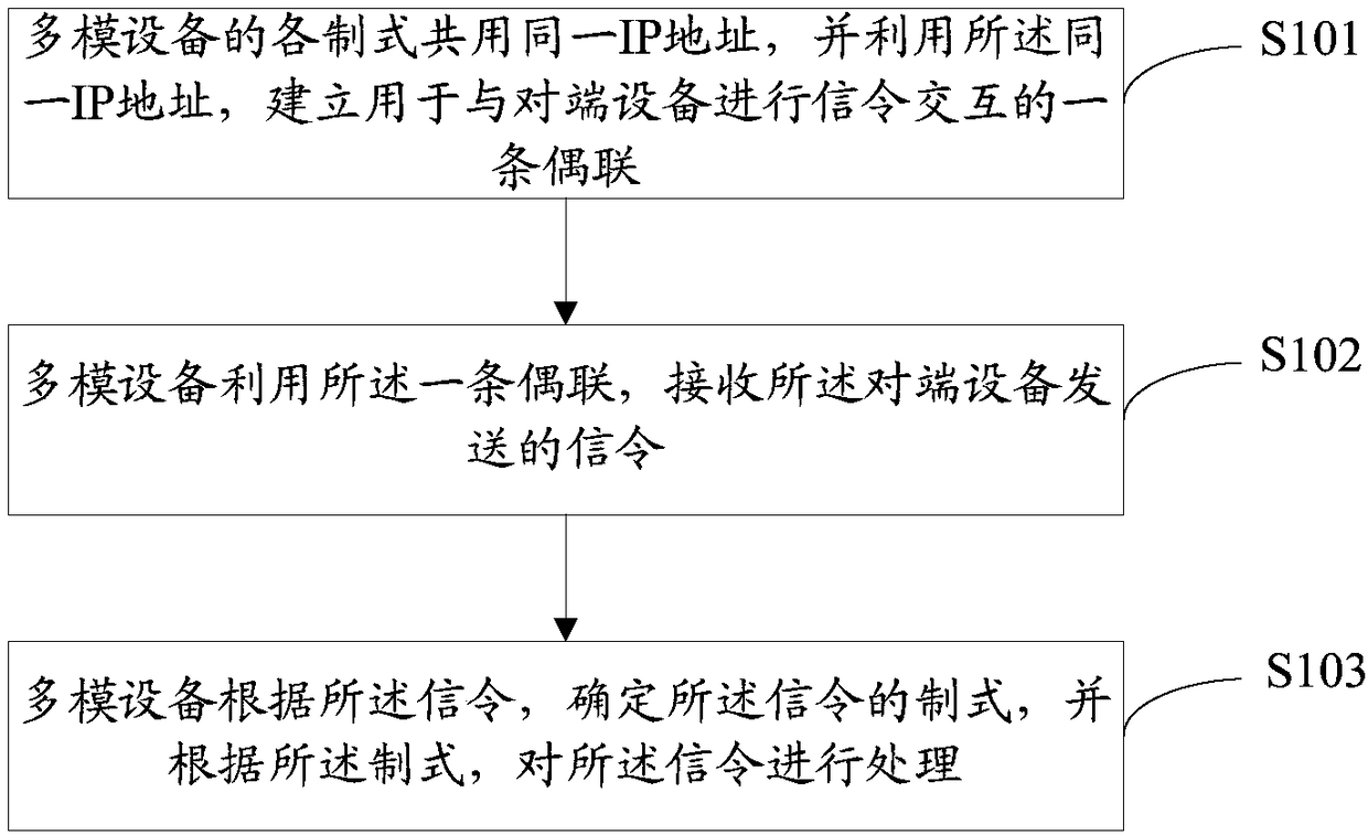
[0039] figure 2 is a block diagram of the multi-system co-coupling method provided by the embodiment of the present invention, such as figure 2 As shown, the steps include:

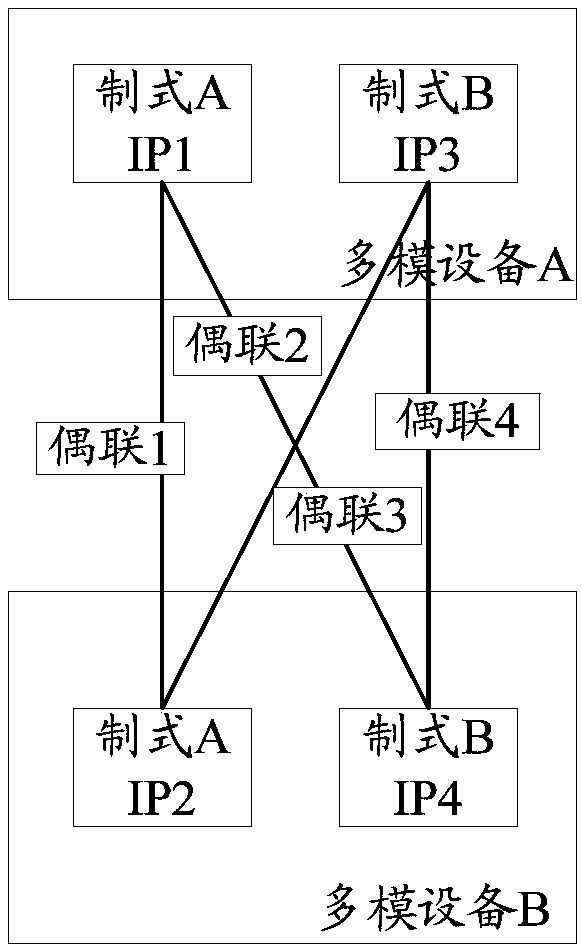
[0040] Step S101: Each system of the multi-mode device shares the same IP address, and uses the same IP address to establish a connection for signaling interaction with the peer device.

[0041] Step S102: the multimode device uses the one coupling to receive the signaling sent by the peer device.

[0042] Step S103: The multi-mode device determines a system of the signaling according to the signaling, and processes the signaling according to the system.

[0043] Step S103 inclu...


PUM


Abstract

The invention discloses a multi-system co-coupling method and device, and relates to the technical field of signal receiving and sending with an SCTP (Stream Control Transmission Protocol). The methodcomprises the following steps: sharing the same Internet protocol (IP) address among the systems of multimode equipment, and establishing a coupling for performing signaling interaction with oppositeend equipment with the same IP address; receiving a signal sent by the opposite end equipment with the multimode equipment through the coupling; and determining the system of the signal by the multimode equipment, and processing the signal according to the system. In the embodiment of the invention, the plurality of systems share one SCTP coupling, so that the coupling number among the multimodeequipment is reduced greatly, and operator IP resources and equipment memory resources are saved.

Description

technical field [0001] The present invention relates to the technical field of sending and receiving signaling by using Stream Control Transmission Protocol (Stream Control Transmission Protocol, SCTP), in particular to a multi-system co-coupling method and device. Background technique [0002] As a reliable transmission protocol, the SCTP protocol is adopted by multiple 2, 3, and 4G systems such as Global System For Mobile Communication (GSM) / Universal Mobile Telecommunications System (UMTS) / Long Term Evolution (LTE) Widely used to improve reliable sending and receiving channels for high-level signaling. At present, when multi-mode equipment is planned and deployed, each standard has its own Internet Protocol (Internet Protocol, IP) address and association. figure 1 It is a schematic diagram of multi-system different couplings provided by the prior art, such as figure 1 As shown, multimode device A includes standard A and standard B, standard A plans and allocates IP1, st...

Claims


Application Information

Patent Timeline
Patent Type & Authority Applications(China)
IPC IPC(8): H04W8/26H04W76/11H04W88/10H04W92/20
CPCH04W8/26H04W92/20H04W88/10
Inventor 黄海涛
Owner ZTE CORP
Why Eureka
Try Eureka