White plume elimination system for flue gas and method using white plume elimination system
A flue gas and whitening technology, which is applied in the field of flue gas whitening system, can solve the problems of increased energy consumption and non-compliance, and achieve the effects of reducing water content, simple structure, and improving whitening efficiency
- Summary
- Abstract
- Description
- Claims
- Application Information
AI Technical Summary
Problems solved by technology
Method used
Image

Examples
Example Embodiment
[0025] Example 1
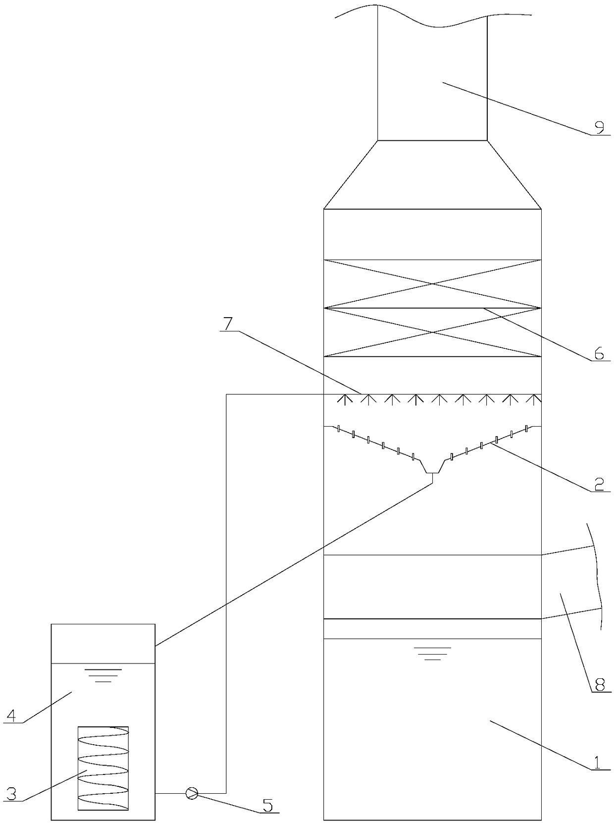
[0026] A flue gas whitening system, including a desulfurization tower 1, an immersed U-shaped tube bundle slurry cooling device 3, a circulation tank 4 and a circulation pump 5. The desulfurization tower 5 is sequentially provided with a mist eliminator 6, a spray layer from top to bottom 7 and the inverted quadrangular pyramid circular slurry collection device 2, the immersed U-shaped tube bundle slurry cooling device 3 is set in the circulating tank 4, the outlet of the circulating tank 4 is connected with the inlet of the circulating pump 5, and the outlet of the circulating pump 5 is connected to the desulfurization tower 1. The slurry inlet is connected, and the outlet of the inverted quadrangular pyramid-shaped circulating slurry collecting device 2 is connected with the inlet of the circulating tank 4. The desulfurization tower 1 is also provided with a desulfurization tower flue gas inlet 8 and a desulfurization tower flue gas outlet 9.
[0027] Use the ...
Example Embodiment
[0029] Example 2
[0030] A flue gas whitening system, including a desulfurization tower 1, an immersed U-shaped tube bundle slurry cooling device 3, a circulation tank 4 and a circulation pump 5. The desulfurization tower 5 is sequentially provided with a mist eliminator 6, a spray layer from top to bottom 7 and the inverted cone-shaped circulating slurry collecting device 2, the immersed U-shaped tube bundle slurry cooling device 3 is set in the circulating tank 4, the outlet of the circulating tank 4 is connected with the inlet of the circulating pump 5, and the outlet of the circulating pump 5 is connected with the desulfurization tower 1 The slurry inlet is connected, and the outlet of the inverted cone-shaped circulating slurry collecting device 2 is connected with the inlet of the circulating tank 4. The desulfurization tower 1 is also provided with a desulfurization tower flue gas inlet 8 and a desulfurization tower flue gas outlet 9.
[0031] Use the above-mentioned flue ...
Example Embodiment
[0033] Example 3
[0034] A flue gas whitening system, comprising a desulfurization tower 1, an immersed floating head tube type slurry cooling device 3, a circulation tank 4 and a circulation pump 5. The desulfurization tower 5 is sequentially provided with a mist eliminator 6, a spray layer from top to bottom 7 and the inverted quadrangular pyramid circular slurry collection device 2, the immersed floating head tube type slurry cooling device 3 is arranged in the circulating tank 4, the outlet of the circulating tank 4 is connected with the inlet of the circulating pump 5, and the outlet of the circulating pump 5 is connected to the desulfurization tower 1 The slurry inlet is connected, and the outlet of the inverted quadrangular pyramid-shaped circulating slurry collecting device 2 is connected with the inlet of the circulating tank 4. The desulfurization tower 1 is also provided with a desulfurization tower flue gas inlet 8 and a desulfurization tower flue gas outlet 9.
[003...
PUM
| Property | Measurement | Unit |
|---|---|---|
| Density | aaaaa | aaaaa |
Abstract
Description
Claims
Application Information
 - R&D Engineer
- R&D Manager
- IP Professional
- Industry Leading Data Capabilities
- Powerful AI technology
- Patent DNA Extraction
Browse by: Latest US Patents, China's latest patents, Technical Efficacy Thesaurus, Application Domain, Technology Topic.
© 2024 PatSnap. All rights reserved.Legal|Privacy policy|Modern Slavery Act Transparency Statement|Sitemap