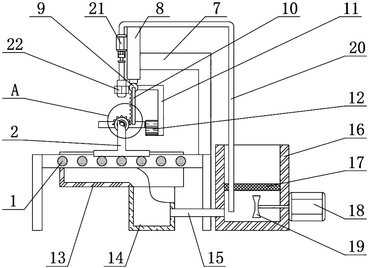
Plate paint spraying device for electric fire box production

A technology of electric fire box and plate, applied in the direction of spray device, etc., can solve the problems of affecting the gloss and feel of the paint surface, paint falling on the outside of the plate, time-consuming and labor-intensive, etc., to ensure the gloss and feel, to facilitate stable splicing, and huge safety benefits. Effect

CN109433459AInactive Publication Date: 2019-03-08苏州家望宝科技有限公司
0 Cites 1 Cited by

Patent Information

Authority / Receiving Office
CN · China
Patent Type
Applications(China)
Current Assignee / Owner
Publication Date
2019-03-08
Estimated Expiration
Not applicable · inactive patent

Smart Images

  • Figure 1
    Figure 1
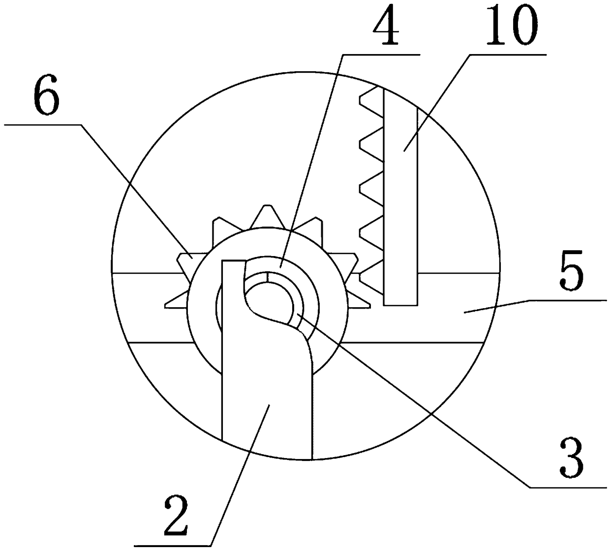
  • Figure 2
    Figure 2
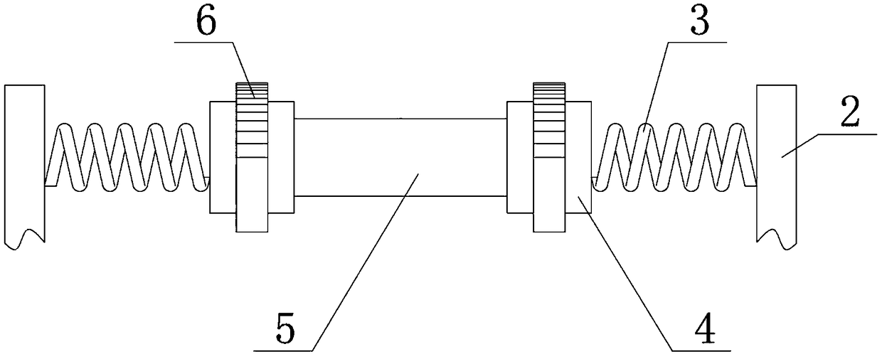
  • Figure 3
    Figure 3
Patent Text Reader

Abstract

The invention relates to the technical field of plate paint spraying, in particular to a plate paint spraying device for electric fire box production. The device comprises a rolling barrel conveyor and a support; the top ends of the rolling barrel conveyor on the front side and the rear side are rotationally connected with the bottom end of the support, a spring is fixedly connected to the rear end of the support at the front side, and a rubber disc is rotationally connected to the rear end of the spring at the front side; a horizontally arranged plate is arranged at the rear end of the rubberdisc at the front side, and a gear is fixedly connected to the outer side of the rubber disc, the reverse rotation of the plate is realized through the rubber disc. According to the device, the rubber disc, the gear and a rack are arranged, the reverse rotation of the plate is realized, painting of the back face and the side face of the plate are facilitated, the side face of the plate is prevented from being affected with damp deformation, the electric fire box can be conveniently and stably spliced, manual painting is not needed, time and labor are saved, leakage coating is prevented, and quality of a finished product paint plate is guaranteed; and the design concept is ingenious, the design is reasonable, huge safety benefits and wide application prospects are achieved, and the deviceis worthy of popularization and use.
Need to check novelty before this filing date? Find Prior Art

Description

Technical field

[0001] The invention relates to the technical field of panel paint spraying, in particular to a panel paint spraying device for electric fire box production. Background technique

[0002] Electric fire boxes are also called electric fire barrels, stoves, solid wood heaters, etc. Electric fire boxes are the latest technological products developed on the basis of traditional fire boxes combined with modern electric heating technology and advanced craftsmanship. Bake dry shoes, insoles, clothing, quilts, etc., as well as an electric fire box that can be used to warm your feet or the room. The heating plate of the electric fire box is placed in a wooden box, and the heating plate has a wooden strip grid and The wooden boxes are fixed together. An adjustable temperature control switch is installed on the wooden box. One lead wire of the adjustable temperature switch is connected to the live wire of the power supply, and the other lead wire is connected in series with a...

Examples

Embodiment Construction

[0019] The technical solutions in the embodiments of the present invention will be clearly and completely described below in conjunction with the accompanying drawings in the embodiments of the present invention. Obviously, the described embodiments are only a part of the embodiments of the present invention, rather than all the embodiments. Based on the embodiments of the present invention, all other embodiments obtained by those of ordinary skill in the art without creative work shall fall within the protection scope of the present invention.

[0020] See Figure 1-3 , The present invention provides a technical solution:

[0021] A panel paint spraying device for electric fire box production, comprising a roller conveyor 1 and a bracket 2. The top ends of the roller conveyor 1 on the front and rear sides are rotatably connected with the bottom end of the bracket 2, and the rear end of the bracket 2 on the front side is fixed A spring 3 is connected, the rear end of the spring 3 ...