
Steering hydraulic oil cooling device for commercial vehicle

A technology for steering hydraulic and cooling devices, which is applied to steering mechanisms, fluid steering mechanisms, power steering mechanisms, etc. It can solve problems such as poor heat dissipation effect and complex pipeline structure, and achieve good heat dissipation effect, good heat dissipation effect, and smooth flow. Effect

Pending Publication Date: 2019-03-08
DONGFENG COMML VEHICLE CO LTD
View PDF12 Cites 2 Cited by
  • Summary
  • Abstract
  • Description
  • Claims
  • Application Information

AI Technical Summary

Problems solved by technology

[0006] The purpose of the present invention is to overcome the defects and problems of complex pipeline structure and poor heat dissipation effect in the prior art, and provide a steering hydraulic oil cooling device for commercial vehicles with simple pipeline structure and good heat dissipation effect

Method used


Image

  • Steering hydraulic oil cooling device for commercial vehicle
  • Steering hydraulic oil cooling device for commercial vehicle
  • Steering hydraulic oil cooling device for commercial vehicle

Examples


Embodiment 1

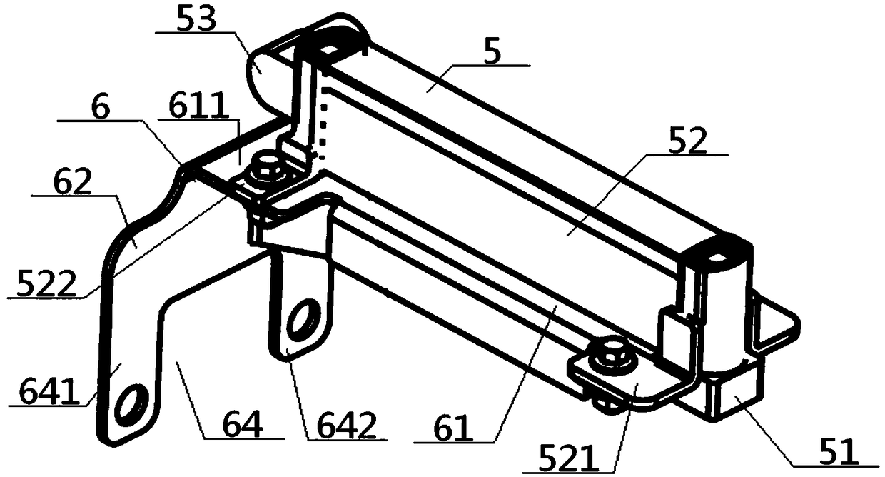
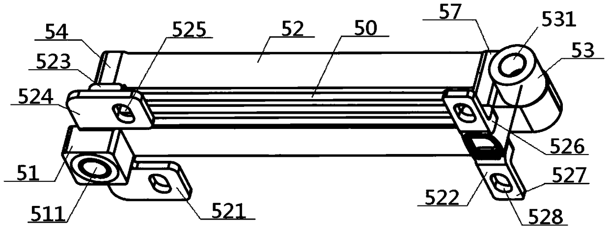
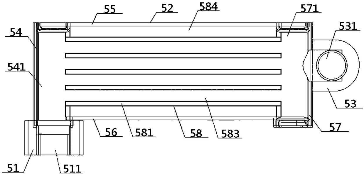
[0058] see Figure 1 to Figure 9 , a steering hydraulic oil cooling device for commercial vehicles, comprising a steering oil temperature radiator 5 and a radiator bracket 6, the steering oil temperature radiator 5 is connected to the vehicle frame 1 through the radiator bracket 6; the steering The oil temperature radiator 5 includes an oil inlet end 51, a heat dissipation body 52 and an oil outlet end 53. The heat dissipation body 52 includes an oil inlet column 54, an upper connecting plate 55, a lower connecting plate 56 and an oil outlet column 57. The oil inlet The bottom end of the column 54 is connected with the top of the oil inlet port 51, and the upper and lower ends of the inner surface of the oil inlet column 54 respectively go through the upper and lower ends of the upper connecting plate 55, the lower connecting plate 56 and the inner surface of the oil outlet column 57. The lower two ends are connected correspondingly, the outer surface of the oil outlet column ...

Embodiment 2

[0060] Basic content is the same as embodiment 1, the difference is:

[0061] A plurality of cooling fins 59 are arranged between the upper connection plate 55 and the adjacent heat dissipation layer 58, between the lower connection plate 56 and the adjacent heat dissipation layer 58, and between the adjacent heat dissipation layer 58. Two ends of the heat sink 59 are vertically connected with the upper connection plate 55 , the lower connection plate 56 or the heat dissipation layer 58 that are in contact with it.

Embodiment 3

[0063] Basic content is the same as embodiment 1, the difference is:

[0064] The front and rear sides of the outer surface of the oil inlet column 54 near the oil inlet end 51 are respectively connected to an oil inlet bracket 521, and the front and rear sides of the outer surface of the oil outlet column 57 near its bottom end are respectively connected to each other. The rear side is connected with an oil outlet bracket 522 respectively, and the oil inlet bracket 521 and the oil outlet bracket 522 are both connected with the vehicle frame 1 through the radiator bracket 6 .

[0065] Preferably, the oil inlet bracket 521 includes an oil inlet vertical plate 523 and an oil inlet horizontal plate 524, the inner surface of the oil inlet vertical plate 523 is connected with the outer surface of the oil inlet column 54, and the bottom end of the oil inlet vertical plate 523 is connected with the oil inlet horizontal plate 524. One end of the plate 524 is vertically connected, the ...


PUM


Abstract

The invention discloses a steering hydraulic oil cooling device for a commercial vehicle. The device comprises a steering oil temperature cooler and a cooler support. The steering oil temperature cooler comprises an oil inlet end, a cooling body and an oil outlet end; the cooling body comprises an oil inlet column, an upper connecting plate, a lower connecting plate and an oil outlet column, the bottom end of the oil inlet column is connected with the top end of the oil inlet end, the upper and lower ends of the inner surface face of the oil inlet column are correspondingly connected with theupper and lower ends of the inner side face of the oil outlet column through the upper and lower connecting plates respectively, the outer side face of the oil outlet column is connected with the oiloutlet end, a plurality of parallel cooling layer plates are arranged between the upper and lower connecting plates, oil cavities inside the cooling layer plates, the oil inlet end, the oil outlet end, the oil inlet column and the oil outlet column are communicated integrally, and the outer side faces of the oil inlet and outlet columns are connected with a vehicle frame through the cooler support. The pipeline structure is simple, the cooling effect is good, the assembling difficulty is low, firmness is high, and the weight is low.

Description

technical field [0001] The invention relates to a heat dissipation device, in particular to a steering hydraulic oil cooling device for commercial vehicles, which is particularly suitable for enhancing heat dissipation effect and simplifying structural design. Background technique [0002] At present, engineering vehicles usually use hydraulic power steering pipeline system to realize steering assist function. Among them, electric engineering vehicles use electrohydraulic power steering pipeline system to realize steering assist function. However, most of the above engineering vehicles do not have steering pipeline system. Design oil temperature radiator. When working for a long time, especially when working for a long time on an engineering vehicle with harsh working conditions, the temperature of the steering hydraulic oil will rise rapidly. When it reaches a certain temperature, the steering hydraulic oil will become thinner and its performance will deteriorate. In addit...

Claims


Application Information

Patent Timeline
Patent Type & Authority Applications(China)
IPC IPC(8): B62D5/06
CPCB62D5/06B62D5/062
Inventor 汤超郑锐
Owner DONGFENG COMML VEHICLE CO LTD
Learn More