Oil field heat exchanger

A technology for heat exchangers and oil fields, which is applied in the types of heat exchangers, indirect heat exchangers, lighting and heating equipment, etc. It can solve the problems that high-temperature exhaust gas cannot be used, the heating of oil is not complete, and the flow rate of oil is slow. Resource utilization, avoiding uneven heating, and thorough heating effect

Active Publication Date: 2021-09-21
东营兴盛特种设备科技有限公司
View PDF6 Cites 0 Cited by
  • Summary
  • Abstract
  • Description
  • Claims
  • Application Information

AI Technical Summary

Problems solved by technology

[0004] (1) The oil is simply heated by the heat source, which requires a large amount of heat source. At the same time, a large amount of high-temperature exhaust gas generated by the gas generator during power generation cannot be used, and is directly discharged into the air, resulting in a waste of a large amount of heat source;
[0005] (2) In the process of heating the oil, stagnation is easy to occur at the inflection point of the heat exchanger, which makes the flow rate of the oil slow and the heat exchange efficiency is low;
[0006] (3) In the process of oil supply, since the inlet and outlet of the oil are located at the same end of the device, mutual penetration is likely to occur, resulting in incomplete heating of the oil and uneven heating

Method used


Image

  • Oil field heat exchanger
  • Oil field heat exchanger
  • Oil field heat exchanger

Examples


Embodiment Construction

[0034] The following will clearly and completely describe the technical solutions in the embodiments of the present invention with reference to the accompanying drawings in the embodiments of the present invention. Obviously, the described embodiments are only some of the embodiments of the present invention, not all of them. Based on the embodiments of the present invention, all other embodiments obtained by persons of ordinary skill in the art without making creative efforts belong to the protection scope of the present invention.

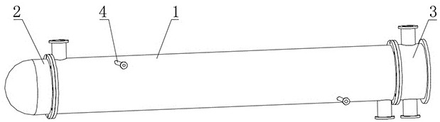
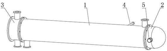
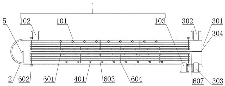
[0035] Please also refer to Figure 1-Figure 7 , wherein, an oil field heat exchanger includes a shell mechanism 1, a side sealing mechanism 2, a feed sealing mechanism 3, a feeding mechanism 5 and a heat exchange mechanism 6.

[0036] In order to provide a heat exchange cavity, the shell mechanism 1 includes a pipe body 101, and two ends of the pipe body 101 are oppositely provided with a heat medium outlet nozzle 102 and a heat medium inlet noz...


PUM


Abstract

The invention relates to the technical field of heat exchangers, and discloses an oil field heat exchanger. The oil field heat exchanger comprises a shell mechanism, a side sealing mechanism, a feeding sealing mechanism, a feeding mechanism and a heat exchange mechanism. The shell mechanism comprises a pipe body, and a heating medium liquid outlet pipe opening and a heating medium liquid inlet pipe opening are oppositely formed in the two ends of the pipe body. The side sealing mechanism comprises a side sealing cover, the top end of the side sealing cover is of a hemispherical structure, a supporting base is arranged on the side face of the side sealing cover, and the side face of the side sealing cover is in sealing connection with the tail end of the pipe body through a flange plate. The feeding sealing mechanism comprises a feeding sealing cover, the feeding sealing cover is in sealing connection with the top end of the pipe body through a flange plate, a refrigerant liquid outlet is formed in the top face of the feeding sealing cover, and a refrigerant liquid inlet is formed in the bottom face of the feeding sealing cover. According to the oil field heat exchanger, high-temperature tail gas can be used for heating heating medium liquid, the cooling rate of the heating medium liquid is reduced, then the heating efficiency of oil can be improved, and therefore loss of heating medium liquid resources is reduced.

Description

technical field [0001] The invention relates to the technical field of heat exchangers, in particular to a heat exchanger for oil fields. Background technique [0002] A large amount of associated gas will be produced in the process of oilfield exploitation. Most of the associated gases are methane, ethane, and propane. Generally, these associated gases will be burned by gas generators to make full use of energy. At the same time, the oilfield exploitation process It is also necessary to heat the oil through a heat exchanger. [0003] However, the existing heat exchangers for oil fields have the following defects in use: [0004] (1) The oil is simply heated by the heat source, which requires a large amount of heat source. At the same time, a large amount of high-temperature exhaust gas generated by the gas generator during power generation cannot be used, and is directly discharged into the air, resulting in a waste of a large amount of heat source; [0005] (2) In the pr...

Claims


Application Information

Patent Timeline
IPC IPC(8): F28D7/00F28D7/16
CPCF28D7/0083F28D7/16
Inventor 吕宪雷袁德锋唐杨兵
Owner 东营兴盛特种设备科技有限公司
Why Eureka
Try Eureka