Composite material rectangular tube floating body stand system floating on water for photovoltaic power generation and manufacturing and mounting process for composite material rectangular tube floating body stand system

A composite material and photovoltaic power generation technology, which is applied to floating buildings, transportation and packaging, ship parts, etc., can solve the problems that it is difficult to meet the 25-year life cycle requirements of photovoltaic power plants, achieve mass production and improve service life , The effect of convenient installation and construction

Pending Publication Date: 2019-03-08
NANJING UNIV OF TECH +1
View PDF10 Cites 2 Cited by
  • Summary
  • Abstract
  • Description
  • Claims
  • Application Information

AI Technical Summary

Problems solved by technology

The floating unit in the existing floating platform is usually made of high-density polyethylene material, and its service life is about 10-15 years, which is difficult to meet the requirements of the 25-year life cycle of photovoltaic power plants

Method used


Image

  • Composite material rectangular tube floating body stand system floating on water for photovoltaic power generation and manufacturing and mounting process for composite material rectangular tube floating body stand system
  • Composite material rectangular tube floating body stand system floating on water for photovoltaic power generation and manufacturing and mounting process for composite material rectangular tube floating body stand system
  • Composite material rectangular tube floating body stand system floating on water for photovoltaic power generation and manufacturing and mounting process for composite material rectangular tube floating body stand system

Examples


Embodiment Construction

[0034] The present invention will be further described below in conjunction with the accompanying drawings and specific embodiments.

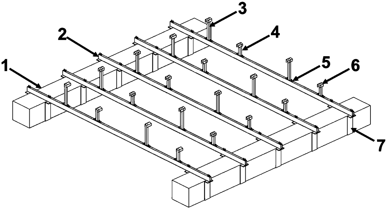
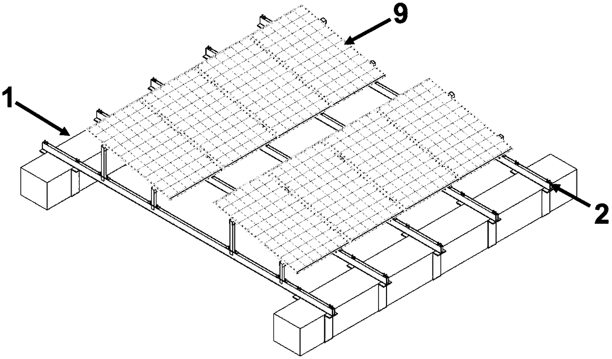
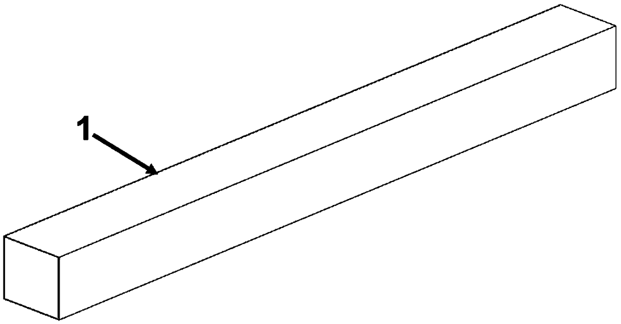
[0035] Such as figure 1As shown in -9, a composite material rectangular tube floating body mounting system for floating photovoltaic power generation on water, the floating body mounting system includes a composite material rectangular tube floating body main beam 1, galvanized steel, composite material or aluminum alloy rectangular tube floating body secondary beam 2 and galvanized steel, composite or aluminum alloy railless brackets.

[0036] The connection between the main girder 1 of the composite rectangular tube floating body and the secondary beam 2 of the rectangular tube floating body made of galvanized steel, composite material or aluminum alloy is divided into two types: 1. along the axial direction of the main girder 1 of the rectangular tube floating body made of composite material The groove-shaped composite material hoops 7 are ...


PUM

PropertyMeasurementUnit
Lengthaaaaaaaaaa
Lengthaaaaaaaaaa

Abstract

The invention discloses a composite material rectangular tube floating body stand system floating on water for photovoltaic power generation and a manufacturing and mounting process for the compositematerial rectangular tube floating body stand system. The floating body stand system comprises composite material rectangular tube floating body main beams, galvanized steel, composite material or aluminum alloy rectangular tube floating body secondary beams and galvanized steel and composite material or aluminum alloy guide-track-free supports. According to a mode of connecting the composite material rectangular tube floating body main beams, after being aligned and connected, ends of the composite material rectangular tube floating body main beams are inserted in a groove type composite material hoops, and the tops of the groove type composite material hoops are closed; and the composite material rectangular tube floating body main beams are connected with the galvanized steel and the composite material or aluminum alloy rectangular tube floating body secondary beams through groove type composite material hoops and stainless steel bolts or manual pasting composite materials, and a plurality of composite material floating body units are assembled to form a whole body in the longitudinal direction and the transverse direction. The structural component can be applied to constructionof a water photovoltaic power station quite well, and the requirement for the service life period of 25 years of a photovoltaic power station is met.

Description

technical field [0001] The invention relates to the field of construction of floating photovoltaic power stations on the water surface, and specifically relates to a composite material floating body mounting system and its installation process that are green and environmentally friendly, have a long life cycle, low maintenance costs, and are applied to photovoltaic power generation on water. Background technique [0002] In recent years, with the continuous development of my country's social economy, my country's photovoltaic power generation industry has entered a stage of rapid development. As of the end of 2017, my country has become the world's largest photovoltaic market. At present, my country's photovoltaic power stations are mainly large-scale centralized ground photovoltaic power stations. With the rapid growth of the number, most photovoltaic power generation systems have generally formed two major development problems: one is that the construction project occupie...

Claims


Application Information

Patent Timeline
IPC IPC(8): B63B35/44B63B9/00
CPCB63B35/44B63B2035/4453B63B71/00
Inventor 方海刘伟庆吴启凡庄勇齐玉军方园霍瑞丽韩娟祝露
Owner NANJING UNIV OF TECH
Why Eureka
Try Eureka