Belt type ball adding system

A technology of belt conveying and steel balls, which is applied to conveyor control devices, conveyors, conveyor objects, etc., can solve the problems of large fluctuations in the filling rate of steel balls, large output of balls, and low utilization coefficient of ball mills. Stabilize the filling rate of steel balls and avoid the effect of ball jamming

Pending Publication Date: 2019-03-08
CHINA ENFI ENGINEERING CORPORATION
View PDF0 Cites 0 Cited by
  • Summary
  • Abstract
  • Description
  • Claims
  • Application Information

AI Technical Summary

Problems solved by technology

This underground belt-type ball feeding method has the following disadvantages: first, the bottom of the steel ball warehouse is booing, and the gate is installed at the discharge port, which is easy to jam the ball, resulting in the steel ball warehouse cannot store steel balls, and the utilization factor is low; second, the intermittent type For feeding, the belt scale installed on the belt conveyor under the warehouse has no stable material pressure, and its measurement accuracy is too poor to achieve accurate measurement and addition of balls; thirdly, the amount of steel balls is controlled and adjusted through the fan-shaped gate at the bottom of the steel ball warehouse. The error is large, and the amount of balls per unit time is large, and the time for adding balls online is short, resulting in large fluctuations in the ball filling rate of the ball mill
[0003] The production practice of the above-mentioned underground belt-type ball adding method also shows that the balls are frequently jammed at the fan-shaped gate at the bottom of the steel ball warehouse, resulting in the loss of the storage function of the steel ball warehouse; the measurement error of the belt scale on the belt conveyor is too large, and the measurement is lost. significance

Method used


Image

  • Belt type ball adding system
  • Belt type ball adding system
  • Belt type ball adding system

Examples


Embodiment Construction

[0051] Embodiments of the present invention are described in detail below, examples of which are shown in the drawings, wherein the same or similar reference numerals designate the same or similar elements or elements having the same or similar functions throughout. The embodiments described below by referring to the figures are exemplary only for explaining the present invention and should not be construed as limiting the present invention.

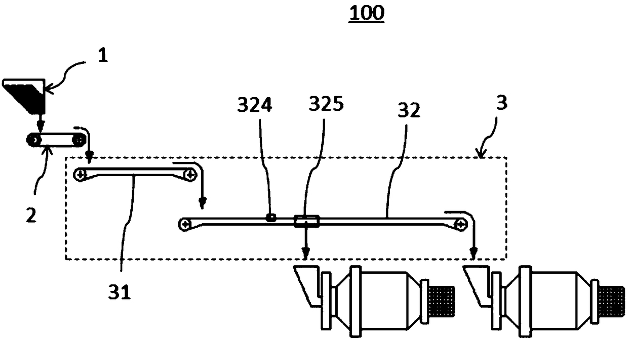
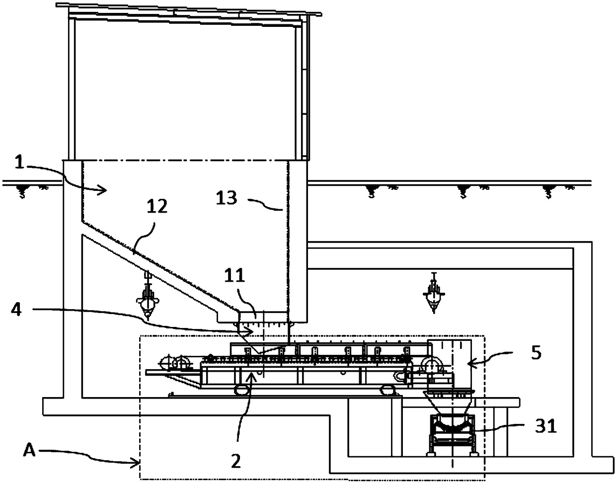
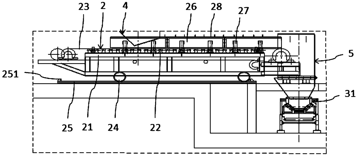
[0052] Refer below Figure 1 to Figure 6 The belt-type ball adding system according to the embodiment of the present invention will be described.

[0053] Such as Figure 1 to Figure 6 As shown, the belt-type ball adding system 100 according to the embodiment of the present invention includes a steel ball bin 1, a low-speed belt-type feeding device 2 and a fast belt-type conveying device 3, wherein at least part of the inner surface of the steel ball bin 1 is self-contained. The top-down inclined surface 12 and the lower end of the inn...


PUM


Abstract

The invention discloses a belt type ball adding system. The belt type ball adding system comprises a steel ball bin, a low-speed belt type feeding device and a quick belt type conveying device, wherein the inner side surface of the steel ball bin is at least provided with a partial inclined surface from top to bottom, and the lower end of the inner side surface defines a shrinking hole; the low-speed belt type feeding device is provided with a dropping end and a discharge end in a conveying direction; the dropping end is positioned below the shrinking hole to receive steel balls dropped from the shrinking hole, and convey the steel balls to the discharge end; and the quick belt type conveying device is positioned below the low-speed belt type feeding device to receive steel balls dropped from the low-speed belt type feeding device and transfer the steel balls to a mill one by one. According to the belt type ball adding system disclosed by the invention, operating speed of the low-speedbelt type feeding device and the quick belt type conveying device is gradually increased, so that the steel balls are superposed in multiple layers for being conveyed on the low-speed belt type feeding device, and are distributed in single layer on the quick belt type conveying device, and therefore, the steel balls are transferred to the mill one by one. Besides, the steel ball bin and the low-speed belt type feeding device can be designed to effectively avoid a ball blocking and arching phenomenon at the shrinking hole.

Description

technical field [0001] The invention relates to the technical field of mill ball addition, in particular to a belt type ball addition system. Background technique [0002] The existing underground belt-type ball feeding method generally adopts fan-shaped gates at the bottom of the underground steel ball warehouse, and the steel balls are transferred to the belt conveyor through the gate funnel. The belt scale is installed on the belt conveyor, and the steel balls are measured by the belt scale. Then add to the ball mill. This underground belt-type ball feeding method has the following disadvantages: first, the bottom of the steel ball warehouse is booing, and the gate is installed at the discharge port, which is easy to jam the ball, resulting in the steel ball warehouse cannot store steel balls, and the utilization factor is low; second, the intermittent type For feeding, the belt scale installed on the belt conveyor under the warehouse has no stable material pressure, and...

Claims


Application Information

Patent Timeline
IPC IPC(8): B65G47/52B65G43/00B65G15/30
CPCB65G15/30B65G43/00B65G47/52
Inventor 邹毅仁孙明俊何荣权张勇冯建伟夏自发
Owner CHINA ENFI ENGINEERING CORPORATION
Why Eureka
Try Eureka