
Intelligent lifting system for river and lake channel gate

A lifting system and gate technology, applied in water conservancy engineering, marine engineering, coastline protection and other directions, can solve problems such as troublesome, easy aging and maintenance of hydraulic parts, complex structure, etc., to reduce labor hours, reduce equipment maintenance difficulty, and improve intelligence. horizontal effect

Inactive Publication Date: 2019-03-08
CHANGSHU CANON ELEVATOR ACCESSORIES
View PDF6 Cites 1 Cited by
  • Summary
  • Abstract
  • Description
  • Claims
  • Application Information

AI Technical Summary

Problems solved by technology

[0002] In water conservancy projects, the gate is one of the important components of hydraulic structures. It can close the orifice of the building according to the needs, and can also open the orifice fully or partially to adjust the upstream and downstream water level and flow, so as to obtain flood control. , water supply, power generation and other benefits, and can also be used to intercept water flow, adjust flow, discharge sediment and floating objects, etc. Cast iron gates are usually set at the inlets and outlets of water intake and water delivery buildings, and they can be opened and closed flexibly and reliably through the gates To exert their functions and benefits and maintain the safety of buildings; the existing gate lifting structure is mostly hydraulic mechanism to drive the gate up and down. In the actual application process, the hydraulic gate lifting system has a relatively complicated structure and hydraulic parts are easy to age and maintenance is relatively troublesome. , and at least two people need to cooperate to complete the task when using it

Method used


Image

  • Intelligent lifting system for river and lake channel gate
  • Intelligent lifting system for river and lake channel gate
  • Intelligent lifting system for river and lake channel gate

Examples


Embodiment Construction

[0022] The preferred embodiments of the present invention will be described in detail below in conjunction with the accompanying drawings, so that the advantages and features of the present invention can be more easily understood by those skilled in the art, so as to define the protection scope of the present invention more clearly.

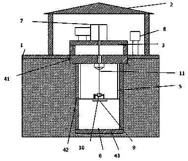
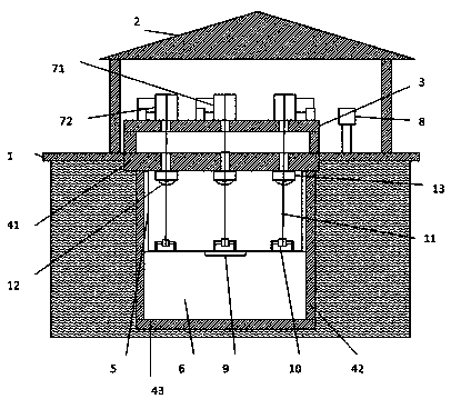
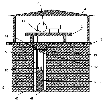
[0023] see figure 1 and image 3 A preferred embodiment of the present invention includes:

[0024] An intelligent lifting system for gates of rivers, lakes and rivers is provided. The intelligent lifting system for gates of rivers, lakes and rivers includes: a gate device, a lifting device and a PLC controller 8; The top plate 41, the side wall 42 and the bottom plate 43 are composed of a groove 5 arranged on the side wall 42 of the load-bearing bracket, and the gate 6 can be vertically displaced along the groove 5 under the drive of the lifting device. The upper top plate 41 of the load-bearing bracket A lifting device is arranged on the plan...


PUM


Abstract

The invention discloses an intelligent lifting system for a river and lake channel gate. The intelligent lifting system for the river and lake channel gate comprises a gate device, a lifting device and a PLC controller. The gate device comprises a bearing bracket and a gate. Grooves are formed in two sides of the bearing bracket. The gate can move perpendicularly along the grooves under the driveof the lifting device. The lifting device is arranged above an upper top plate of the bearing bracket and comprises a traction hoist, a hoist bracket, a traction rope and a rope fixing mechanism whichis arranged below the upper top plate of the bearing bracket. One end of the traction rope is fixed to the gate rope fixing mechanism, and the other end of the traction rope penetrates through a topwheel on a gate top and is connected to a traction rolling hole of the traction hoist. The traction hoist is provided with encoders, each encoder is electrically connected with a PLC controller, and the movement of the traction hoist is controlled by the PLC controllers. By means of the mode, the intelligent lifting system for the river and lake channel gate can take the place of a hydraulic lifting system commonly used at present, thereby alleviating the maintenance difficulty and improving the intelligence level of equipment and the labor efficiency.

Description

technical field [0001] The invention relates to the field of water conservancy equipment, in particular to an intelligent lifting system for gates of rivers, lakes and rivers. Background technique [0002] In water conservancy projects, the gate is one of the important components of hydraulic structures. It can close the orifice of the building according to the needs, and can also open the orifice fully or partially to adjust the upstream and downstream water level and flow, so as to obtain flood control. , water supply, power generation and other benefits, and can also be used to intercept water flow, adjust flow, discharge sediment and floating objects, etc. Cast iron gates are usually set at the inlets and outlets of water intake and water delivery buildings, and they can be opened and closed flexibly and reliably through the gates To exert their functions and benefits and maintain the safety of buildings; the existing gate lifting structure is mostly hydraulic mechanism ...

Claims


Application Information

Patent Timeline
IPC IPC(8): E02B7/26E02B7/36
CPCE02B7/26E02B7/36
Inventor 陈惠良
Owner CHANGSHU CANON ELEVATOR ACCESSORIES
Learn More