Air blocking structure of electric fan

A technology of electric fans and bellows, which is applied to the components of pumping devices for elastic fluids, pump control, non-variable-capacity pumps, etc., can solve the problems of inability to stop and the air baffle occupying the air outlet area.

Active Publication Date: 2019-03-08
宁波市弘露电子商务有限公司
View PDF10 Cites 2 Cited by
  • Summary
  • Abstract
  • Description
  • Claims
  • Application Information

AI Technical Summary

Problems solved by technology

[0006] The present invention intends to provide a windshield structure for electric fans to overcome the problems in the prior art that the original wind field cannot be stopped after changing the wind field, and the windshield occupies part of the wind outlet area

Method used


Image

  • Air blocking structure of electric fan
  • Air blocking structure of electric fan
  • Air blocking structure of electric fan

Examples


Embodiment Construction

[0024] The following is further described in detail through specific implementation methods:

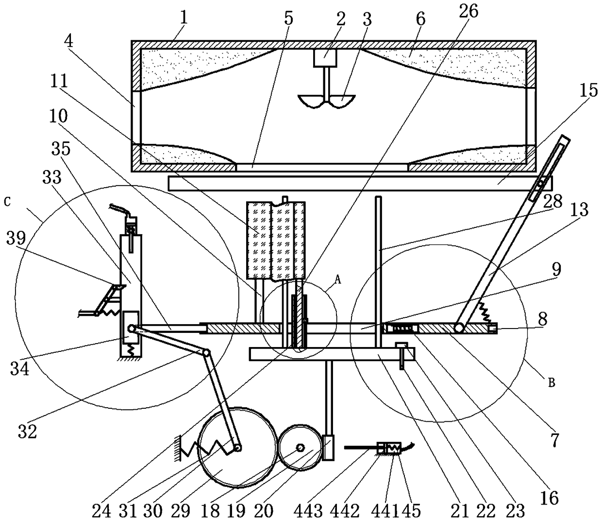
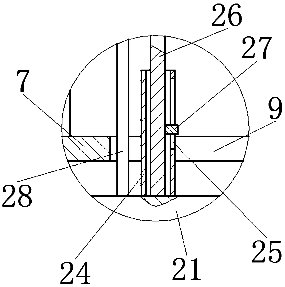
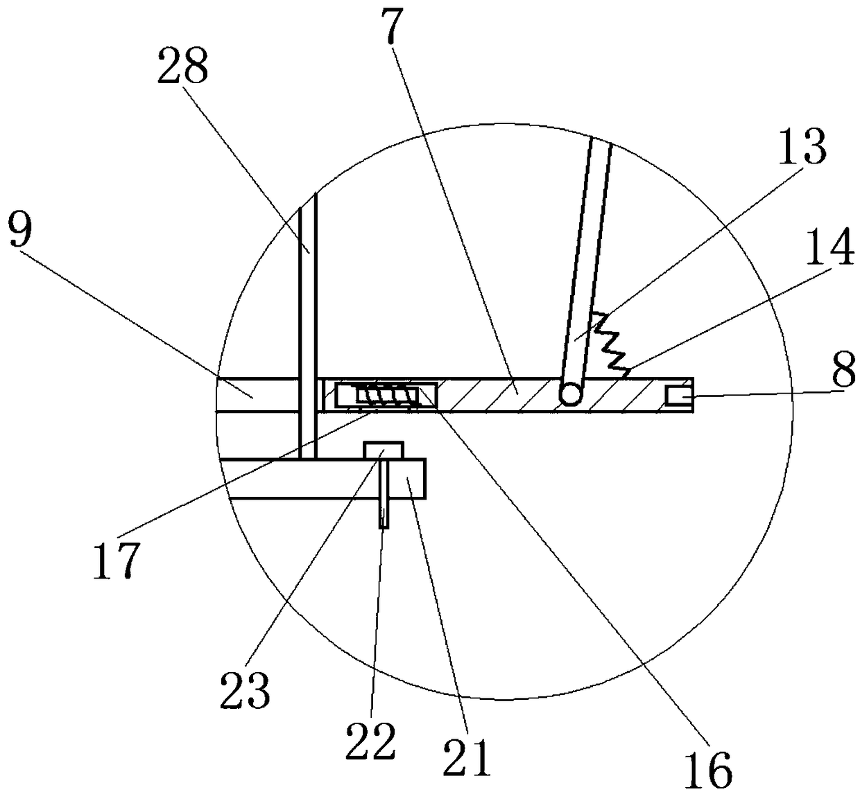
[0025] The reference signs in the drawings of the description include: bellows 1, first motor 2, fan blade 3, air outlet 4, first opening 5, air guide block 6, limit plate 7, annular chute 8, through hole 9, First support column 10, windproof cloth 11, spring leaf 12, first connecting rod 13, limit spring 14, baffle plate 15, electromagnet 16, second opening 17, output end 18 of the second motor, first gear 19 , worm 20, rotating disk 21, latch 22, contact block 23, sleeve 24, chute 25, second support column 26, protrusion 27, limit rod 28, second gear 29, second connecting rod 30, the second A spring 31, the third connecting rod 32, vertical groove 33, slide block 34, moving plate 35, first piston cylinder 36, first piston 371, first piston plate 372, second spring 373, vent pipe 38, wedge-shaped Block 39, the fourth connecting rod 40, the toggle rod 41, the lever strut 42, the fou...


PUM


Abstract

The invention relates to the technical field of electric fans, and discloses an air blocking structure of an electric fan. The air blocking structure comprises a rack and an air bellow, the air bellowis internally provided with a first motor and fan blades, air outlets are formed in the side walls of the air bellow, a first opening is formed in the bottom of the air bellow, a limiting plate is arranged in the rack, a through hole is formed in the center of the limiting plate, a first supporting column is vertically fixed to the surface of the limiting plate, and the upper end of the first supporting column is rotationally connected with a coil stock used blocking air. A second motor is arranged below the limiting plate, the output end of the second motor is fixedly connected with a firstgear, the side wall of the first gear is engaged with a worm and a second gear, the worm is coaxially connected with a rotating disc, and the upper surface of the rotating disc is fixedly connected with a telescopic assembly and limiting bars; the second gear is coaxially connected with a second connecting rod and a third connecting rod; and the rack is internally provided with a limiting mechanism used for controlling the limiting plate to move up and down. By controlling the covering degree of the coil stock between the first supporting rod and the telescopic assembly to the air outlets, theair blocking area is changed.

Description

technical field [0001] The invention relates to the technical field of electric fans, in particular to a windshield structure of electric fans. Background technique [0002] At present, in order to obtain a larger air outlet angle, conventional electric fans mainly have two methods: one is to rotate the fan part, that is, a rotary blade fan, and the other is to change the direction of air flow through the rotation of the wind deflector. [0003] However, the way to rotate the blades or the wind deflector is to completely change the flow direction of the wind field, that is, there is only wind at a certain angle directly opposite the wind outlet. of comfort. [0004] Regarding the above problems, the patent document with the application number 201510486731.6 and the authorized announcement number CN105090115B discloses an electric fan and an air outlet structure, including a driving device, a wind deflector and a linkage mechanism connecting the driving device and the wind d...

Claims


Application Information

Patent Timeline
IPC IPC(8): F04D29/40F04D27/00
CPCF04D27/00F04D29/403
Inventor 岑露明
Owner 宁波市弘露电子商务有限公司
Why Eureka
Try Eureka