Hanging machine and air conditioner with same

An on-hook and cabinet technology, applied in air-conditioning systems, home appliances, mechanical equipment, etc., can solve the problems of poor user experience, low air supply, short air supply distance, etc., to improve user experience, good user experience, Simple and beautiful appearance

Pending Publication Date: 2019-03-08
GD MIDEA AIR-CONDITIONING EQUIP CO LTD +1
View PDF0 Cites 6 Cited by
  • Summary
  • Abstract
  • Description
  • Claims
  • Application Information

AI Technical Summary

Problems solved by technology

[0002] On-hooks in the related art usually use a cross-flow fan for air supply. On the one hand, the air supply distance is short, and it is impossible to achieve long-distance air supply; The wind deflector with micro holes reduces the wind speed, the air volume loss is large, and the air supply volume is low, resulting in poor user experience

Method used


Image

  • Hanging machine and air conditioner with same
  • Hanging machine and air conditioner with same
  • Hanging machine and air conditioner with same

Examples


Embodiment 1

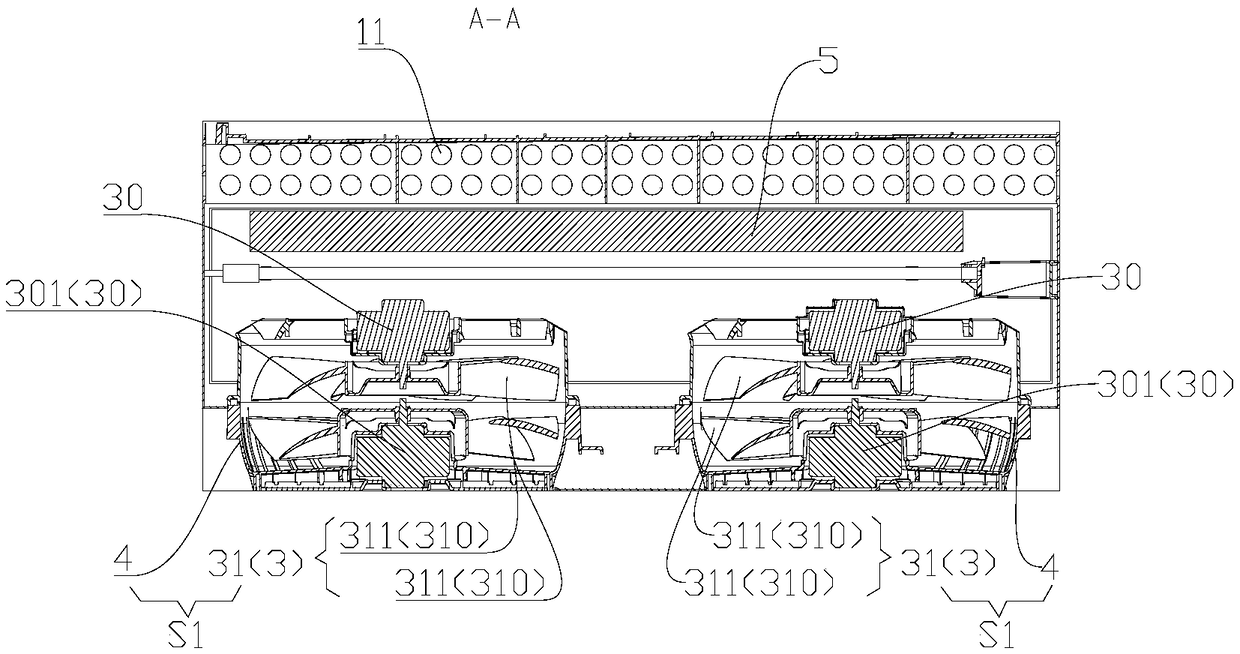
[0100] like Figure 20-Figure 25 As shown, the front side of the casing 10 has a first front air outlet 212, and the lateral sides of the casing 10 (that is, both sides in the horizontal direction, such as Figure 20 The left side and the right side shown in ) respectively have a side air outlet 211, the first air supply part S1 is one and is located at the rear side of the first front air outlet 212, the first fan assembly 3 includes a counter-rotating fan 31, and The axis of the whirlwind fan 31 extends along the front-to-back direction, and the front side of the first air duct member 4 in the first air supply part S1 has a first front air opening 412 (the first front air opening 412 is positioned at the axial front of the cyclone air blower 31 side), the first front vent 412 communicates with the first front air outlet 212 correspondingly, and the lateral sides of the first air duct 4 respectively have side vents 411 (the side vents 411 are located at the radial side of the...

Embodiment 2

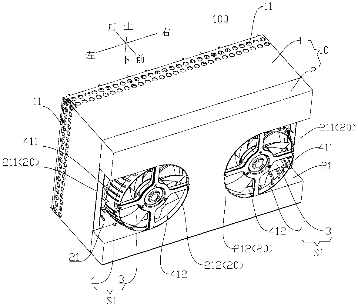
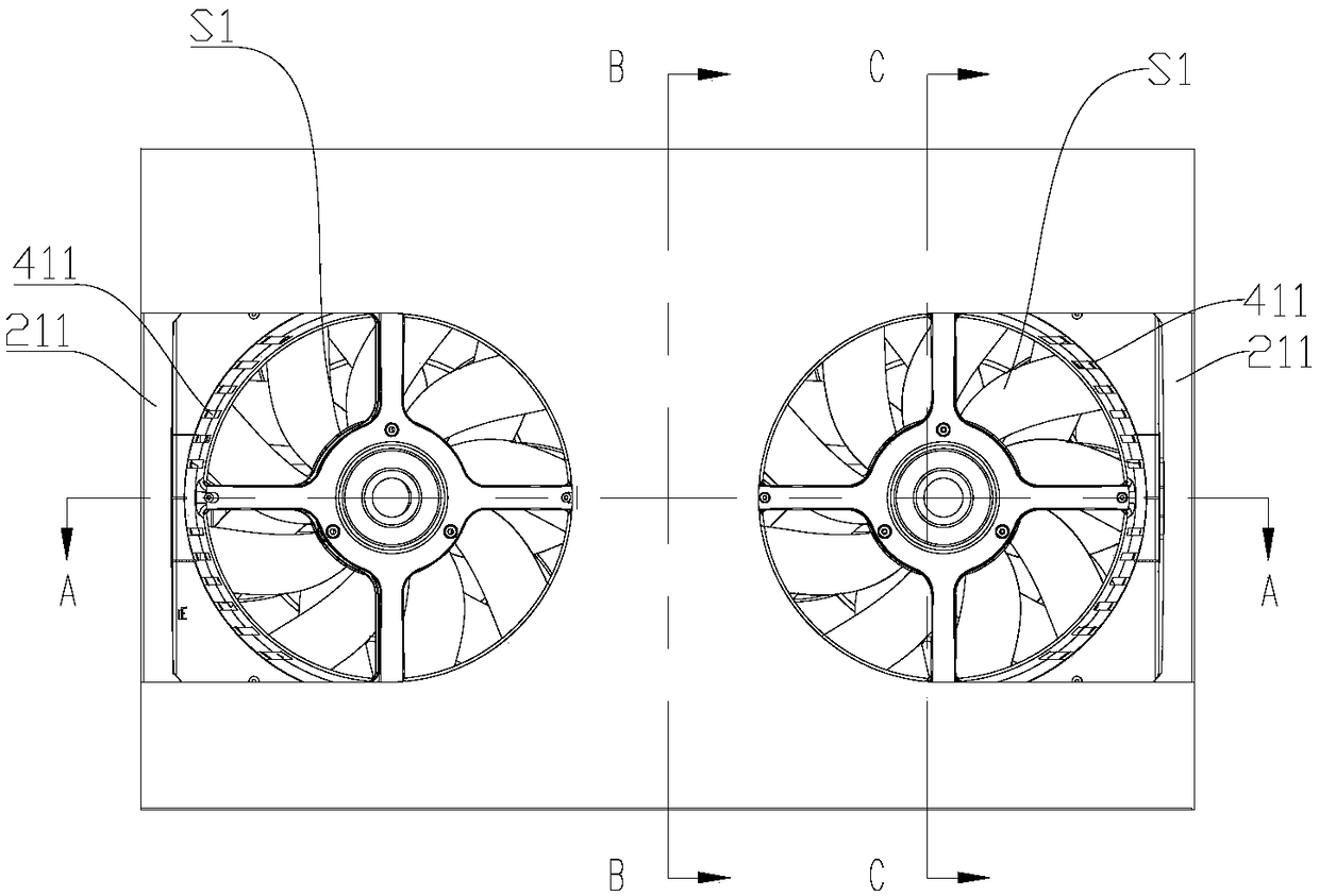
[0105] like Figure 1-Figure 8 As shown, the front side of the casing 10 has two first front air outlets 212, and the two first front air outlets 212 are spaced apart in the lateral direction (that is, spaced apart in the horizontal direction, such as figure 1 As shown in the left and right directions are spaced apart), the lateral sides of the casing 10 (that is, both sides in the horizontal direction, such as figure 1 The left side and the right side shown in ) respectively have a side air outlet 211, and there are two first air supply components S1, and the two first air supply components S1 are spaced apart in the transverse direction to correspond to the two first front air outlets. The rear side of the air outlet 212.

[0106] The front side of the first air duct member 4 in each first air supply component S1 has a first front air opening 412 to communicate with the first front air outlet 212 on the front side thereof, and each first air supply component S1 The lateral...

Embodiment 3

[0114] The structure of the third embodiment is basically the same as that of the second embodiment above, except that the specific structure of the first blower assembly 3 in the first air supply part S1 on the left is different from that of the second embodiment.

[0115] In the third embodiment, if Figure 15 As shown, the first fan assembly 3 of the first air supply part S1 on the left side includes: two axial flow wind wheels 311, and the two axial flow wind wheels 311 are driven by the same motor 30, and the motor 30 is arranged at two The rear side of an axial flow wind wheel 311.

[0116] Thus, when the blades of the two axial flow impellers 311 have the same inclination directions and the two axial flow impellers 311 rotate in the same direction, the two axial flow impellers 311 can both blow air forward. At this time, the left The first fan assembly 3 on the side can have a larger air supply volume, thereby increasing the overall air supply volume of the hanger 100....


PUM


Abstract

The invention discloses a hanging machine and an air conditioner with the same. The hanging machine comprises a machine shell, a heat exchanger and a counter-rotating fan, wherein a wall hanging partused for be hung on a wall is arranged on the machine shell, an air inlet and an air outlet are formed in the machine shell, the heat exchanger is arranged in the machine shell, the counter-rotating fan is arranged in the machine shell, airflow circulates between the air inlet and the air outlet, the counter-rotating fan comprises a first wind wheel and a second wind wheel, the first wind wheel isan axial flow wind wheel or an oblique flow wind wheel, the second wind wheel is an axial flow wind wheel or an oblique flow wind wheel, and the rotation direction of the first wind wheel in which the first wind wheel blows the airflow towards the preset direction is opposite to that of the second wind wheel in which the second wind wheel blows the airflow towards the preset direction. Accordingto the hanging machine, long-distance air supply, wide-angle air supply, soft wind feeling air supply or wind-free feeling air supply can be realized, and the air volume loss is small.

Description

technical field [0001] The invention relates to the technical field of air conditioners, in particular to an on-hook and an air conditioner with the same. Background technique [0002] On-hooks in the related art usually use a cross-flow fan for air supply. On the one hand, the air supply distance is short, and it is impossible to achieve long-distance air supply; The wind deflector with micro holes reduces the wind speed, the air volume loss is large, and the air supply volume is low, resulting in poor user experience. Contents of the invention [0003] The present invention aims to solve at least one of the technical problems existing in the prior art. For this reason, the present invention proposes an on-hook that can realize long-distance air supply, and it can realize soft wind or no wind-sensing air supply with less air volume loss without using an air deflector with micro holes. [0004] The present invention also proposes an air conditioner with the above hook. ...

Claims


Application Information

Patent Timeline
Patent Type & Authority Applications(China)
IPC IPC(8): F24F1/0014F24F1/0033F24F13/02F24F13/06F24F13/20F24F11/77
CPCF24F1/0014F24F1/0033F24F11/77F24F13/02F24F13/06F24F13/20F24F2013/205Y02B30/70
Inventor 袁宏亮张滔陈良锐汪先送周何杰
Owner GD MIDEA AIR-CONDITIONING EQUIP CO LTD
Why Eureka
Try Eureka