Dehumidification drying unit adopting an air inlet precooling and efficient dehumidification combined module and drying device

A pre-cooling and air intake technology, which is applied in the direction of dryers, dryers for static materials, drying, etc., can solve the problems of low proportion of heat and humidity load, lower dew point temperature, lower relative humidity, etc., and achieve an increase in area air volume ratio , The effect of reducing the air volume and reducing the number of operations

Pending Publication Date: 2019-03-08
SHANGHAI BOHAN THERMAL ENERGY TECH CO LTD
View PDF0 Cites 12 Cited by
  • Summary
  • Abstract
  • Description
  • Claims
  • Application Information

AI Technical Summary

Problems solved by technology

[0010] However, in the later stage of the operation of the airflow closed-circuit circulation heat pump drying device, due to the increase in the drying return air temperature, the decrease in relative humidity, and the decrease in dew point temperature, the "smaller" area of ​​the plate heat exchanger originally configured at the air inlet of the evaporator is reduced. It seems powerless, unable to make the evaporator inlet air be effectively pre-cooled to a "sa

Method used


Image

  • Dehumidification drying unit adopting an air inlet precooling and efficient dehumidification combined module and drying device
  • Dehumidification drying unit adopting an air inlet precooling and efficient dehumidification combined module and drying device
  • Dehumidification drying unit adopting an air inlet precooling and efficient dehumidification combined module and drying device

Examples


Embodiment 1

[0044] refer to figure 2 , the present invention provides a dehumidification and drying unit adopting an air inlet precooling and high-efficiency dehumidification combination module, which includes at least two sets of heat pump units, and each set of heat pump units includes a compressor connected in sequence to form a closed system for refrigerant circulation, Condenser, throttling device, internal dehumidification evaporator; also includes a cross-flow heat exchanger BH, cross-flow heat exchanger BH has a cross-flow arrangement of the first heat exchange channel (ie hot fluid channel) and the second heat exchange channel (i.e. the cold fluid channel), the air outlet of the first heat exchange channel and the air inlet of the second heat exchange channel are connected through a circulation channel; the internal dehumidification evaporators of multiple sets of heat pump units are arranged in sequence in the circulation channel and located The air outlet of the first heat exc...

Embodiment 2

[0078] This embodiment is an adjustment made on the basis of Embodiment 2.

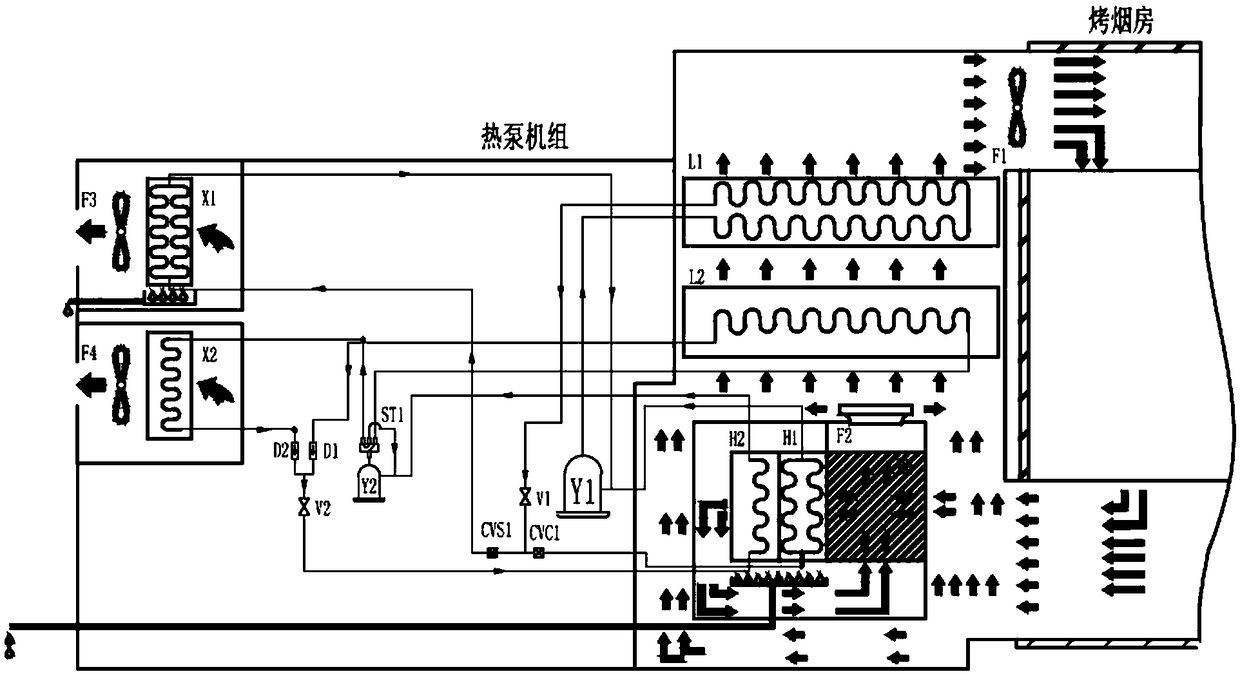
[0079] specific reference image 3 , the dehumidification and drying unit includes two sets of heat pump units, a first heat pump unit and a second heat pump unit.

[0080] In this embodiment, the first heat pump unit includes a first compressor Y1, a first condenser L1, a first throttling device V1, and a first internal dehumidification evaporator H1 connected in sequence; the first heat pump unit also includes a second An outdoor heat exchanger X1, the first outdoor heat exchanger X1 is placed outdoors, and a fan F3 is provided on one side of the first outdoor heat exchanger X1 to promote the flow of outdoor air through the first outdoor heat exchanger X1.

[0081] One end of the first outdoor heat exchanger X1 is connected to the second pipeline between the first internal dehumidification evaporator H1 and the first compressor Y1 through the first pipeline, and the other end is connected to the fi...

Embodiment 3

[0128] This embodiment is an adjustment made on the basis of Embodiment 2.

[0129] specific reference Figure 4 , the dehumidification and drying unit includes two first heat pump units and one second heat pump unit. The specific structural forms of the first heat pump unit and the second heat pump unit refer to the description in Embodiment 2, and will not be repeated here.

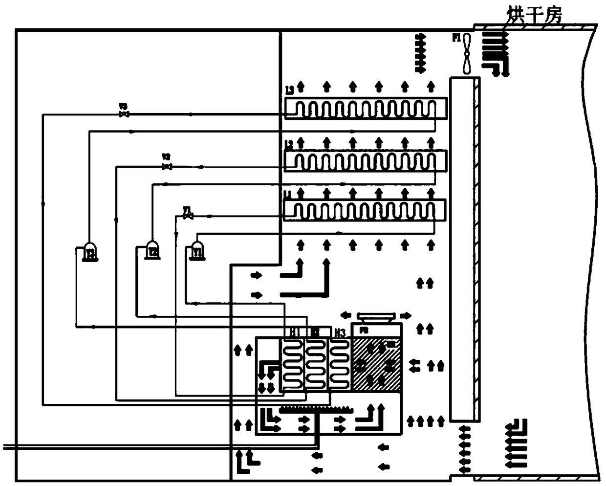
[0130] The dehumidification and drying unit provided in this embodiment adopts the air intake precooling and high-efficiency dehumidification combination module, which serves for the drying of agricultural products such as tobacco leaves. It adopts 3 sets of "one-to-two" refrigeration systems. In an intake air precooling module:

[0131] ① Two sets of one-to-two refrigeration systems for dehumidification and heating in the drying room

[0132] Each system has one condenser and two evaporators. The condensers are installed in the main air duct, and the two sets of evaporators operate at different times...


PUM


Abstract

The invention discloses a dehumidification drying unit adopting an air inlet precooling and efficient dehumidification combined module and a drying device. At least two sets of heat pump units are included, each heat pump unit includes a compressor, a condenser, a throttling device and an internal dehumidification evaporator which are sequentially connected to form a closed system for refrigerantcirculation, and further includes a cross-flow heat exchanger, each cross-flow heat exchanger is provided with a first heat exchange channel and a second heat exchange channel which are arranged alternately, and air outlets of the first heat exchange channels and air inlets of the second heat exchange channels communicate through circulation channels; the internal dehumidification evaporators of the sets of the heat pump units are sequentially arranged in the circulation channels and located at the air outlets of the first heat exchange channels, and air outlets of the second heat exchange channels are provided with first fans; the condensers of the sets of the heat pump units are sequentially arranged at air outlets of the first fans; and drying airflow is cycled in a closed mode, and part of wet air from the drying device flows through the first heat exchange channels, the multiple internal dehumidification evaporators, the circulation channels, the second heat exchange channels, andthe first fans sequentially, is then mixed with the other part of wet air of the drying device, and passes through the multiple condensers to obtain dry air.

Description

technical field [0001] The invention relates to the technical field of dehumidification device design, in particular to a dehumidification drying unit and a drying device using an air intake precooling and high-efficiency dehumidification combination module. Background technique [0002] The heat pump drying device with closed-circuit circulation of air flow is composed of a heat pump hot air unit that produces high-temperature dry air and a drying space that carries wet materials. [0003] as follows figure 1 , in the existing heat pump drying device with closed-circuit circulation of air flow, the high-temperature dry air produced by the heat pump condenser performs heat and moisture exchange with the wet material, captures the moisture in the wet material and returns to the heat pump evaporator as warm and humid air, The evaporator lowers the temperature, dehumidifies and filters out water vapor, and then enters the condenser to absorb heat and heat up. The temperature r...

Claims


Application Information

Patent Timeline
IPC IPC(8): F26B9/06F26B21/00F26B21/04F26B21/08F26B21/10F26B21/12F25B13/00F25B41/04F25B41/06F25B49/02F25B41/20F25B41/30
CPCF25B13/00F25B49/022F26B9/06F26B21/001F26B21/04F26B21/086F26B21/10F26B21/12F26B2200/22F25B41/30F25B41/20
Inventor 薛世山诸葛水明崔国民刘彦中叶子豪薛碧荷詹飞龙李成伟刘玉恩王庆伦
Owner SHANGHAI BOHAN THERMAL ENERGY TECH CO LTD
Why Eureka
Try Eureka