T-joint shear testing device

A shear test and indenter technology, which is used in measuring devices, using a stable shear force to test material strength, instruments, etc., can solve problems such as the inability to simulate pure shear loads and impure shear failures. , to achieve the effect of improving sample efficiency, simplifying sample installation, and simplifying test steps

Pending Publication Date: 2019-03-08
NANJING UNIV OF AERONAUTICS & ASTRONAUTICS +1
View PDF0 Cites 5 Cited by
  • Summary
  • Abstract
  • Description
  • Claims
  • Application Information

AI Technical Summary

Problems solved by technology

[0003] Aiming at the problems existing in the prior art, the present invention discloses a T-joint shear test device. The device is provided with left and right support splints, and the distance can be adjusted to meet the web samples of different thicknesses i

Method used


Image

  • T-joint shear testing device
  • T-joint shear testing device
  • T-joint shear testing device

Examples


Embodiment Construction

[0025] In order to make the object, technical solution and effect of the present invention clearer and clearer, the following examples are given to further describe the present invention in detail. It should be pointed out that the specific implementations described here are only used to explain the present invention, not to limit the present invention.

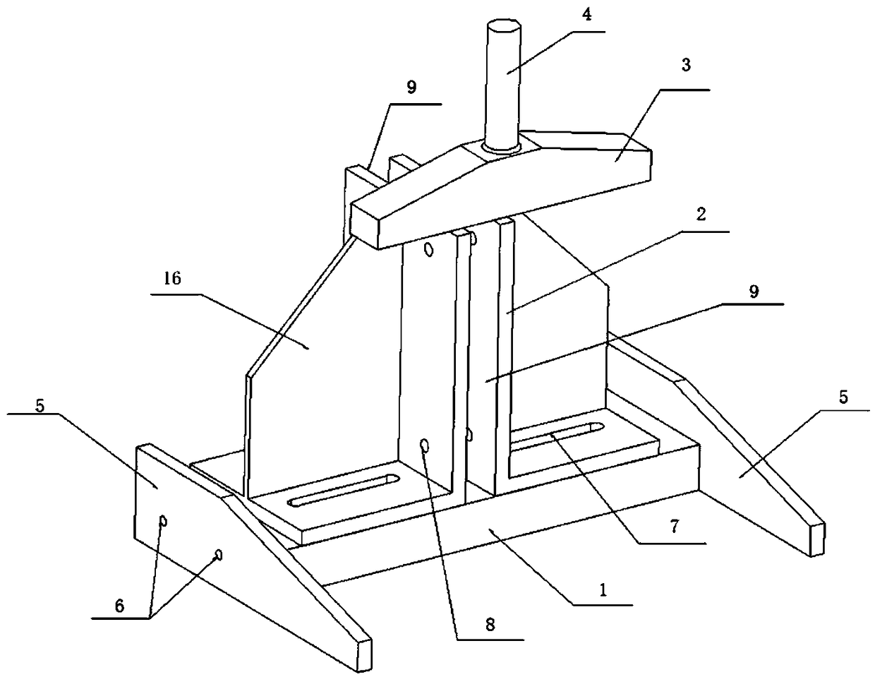
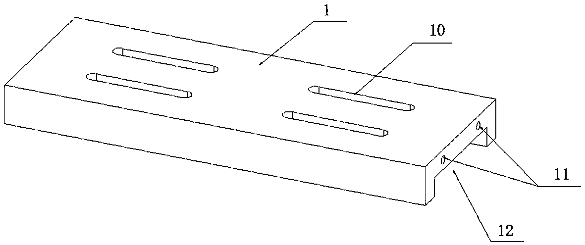
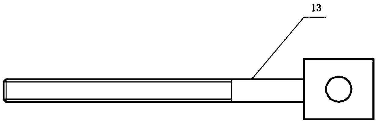
[0026] Such as Figure 1~2 As shown, the main device of the present invention includes a base 1, and support plates 5 are placed on both sides of the base to prevent the test device from tilting due to uneven force. The support plate 5 is a flat plate structure based on an equal rigidity design. Support plate bolt holes 6 are provided on the support plate 5, and base bolt holes 11 are provided on both sides of the base 1. The support plate bolt holes 6 correspond to the opening positions of the base bolt holes 11. image 3 The shown locking bolts 13 respectively pass through the bolt holes 6 of the support plate and the bolt...


PUM


Abstract

The invention discloses a T-joint shear testing device, and belongs to the technical field of testing of the shearing strength of a material. Support plates are arranged on the two sides of a base, supporting clamping plates are symmetrically arranged above the base, a sample is arranged between the supporting clamping plates, a pressing head is transversely arranged above the supporting clampingplates, a base sliding chute is formed in the base, a supporting clamping plate sliding chute is arranged on the lower side of the supporting clamping plate, the base sliding chute and the supportingclamping plate sliding chute correspond in position, a tightening handle penetrates through the supporting clamping plate sliding chute and the base sliding chute to connect the base and the supporting clamping plate; a locating cushion block is further arranged at the upper part of the base; web samples with different thicknesses in a T-joint are met through the distance adjustment of the supporting clamping plate, so that the universality of the testing device is improved; in addition, the clamping mode of the clamping plate guarantees that the loading pressing head applies a pure shear loadonto the sample in the vertical direction, no additional bending moment is produced on the sample in the test process, and the reliability of the shear test is improved.

Description

technical field [0001] The invention belongs to the technical field of material shear strength detection, in particular to a T-shaped joint shear test device. Background technique [0002] The T-joint structure is a connection structure widely used in aerospace, automobile and other fields. It is an important research topic for designers to study the strength of the T-joint structure under different load conditions. Among them, shearing is the main load-bearing form of T-joint structure, and the shear strength of T-joint is obtained through tests to provide a basis for engineering design. However, the currently available T-joint shear test devices cannot simulate the effect of pure shear load well, which may cause non-pure shear damage, and the results of T-joint shear performance tests are often inaccurate, so satisfactory results cannot be obtained. test results. Contents of the invention [0003] Aiming at the problems existing in the prior art, the present invention ...

Claims


Application Information

Patent Timeline
IPC IPC(8): G01N3/24G01N3/04G01N3/02
CPCG01N3/02G01N3/04G01N3/24G01N2203/0025G01N2203/04
Inventor 朱书华张桂嘉王跃全彭益州周进刘显月白树伟汪勇童明波倪彦朝王家军李壮姜炳强张收运
Owner NANJING UNIV OF AERONAUTICS & ASTRONAUTICS
Why Eureka
Try Eureka