
Photoacoustic spectroscopy detection device with self-frequency-modulation noise reduction function

A detection device and photoacoustic spectroscopy technology, which is applied in the direction of measuring devices, material analysis through optical means, instruments, etc., can solve the problems of anti-noise interference and multiple types of interference sources

Active Publication Date: 2019-03-08
INST OF ELECTRICAL ENG CHINESE ACAD OF SCI
View PDF11 Cites 1 Cited by
  • Summary
  • Abstract
  • Description
  • Claims
  • Application Information

AI Technical Summary

Problems solved by technology

However, due to the complex environment of the application site, such as substations, chemical plants, etc., there are many types of interference sources, and the existing photoacoustic spectroscopy detection devices still have some deficiencies in anti-noise interference
The use of simple vibration isolation measures can only reduce noise interference to a certain extent. Lock-in amplification technology is used to lock the modulation frequency of the photoacoustic spectrometer, and only the signal corresponding to the modulation frequency can be detected. However, if there are modulation frequency components in the noise signal, the lock-in Phase amplification principle powerless

Method used


Image

  • Photoacoustic spectroscopy detection device with self-frequency-modulation noise reduction function
  • Photoacoustic spectroscopy detection device with self-frequency-modulation noise reduction function
  • Photoacoustic spectroscopy detection device with self-frequency-modulation noise reduction function

Examples


Embodiment Construction

[0033] The present invention will be further described below in conjunction with the accompanying drawings and specific embodiments.

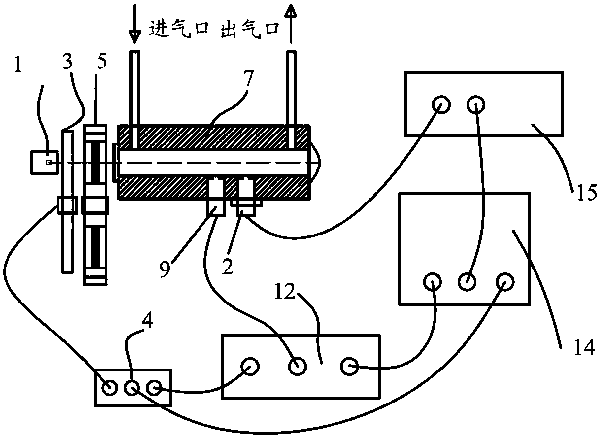
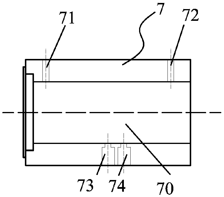
[0034] figure 1 It is a structural schematic diagram of the photoacoustic spectrum detection device with self-frequency modulation and noise reduction function of the present invention. Such as figure 1 As shown, the device of the present invention mainly includes a light source 1, a noise signal detector 2, a mechanical chopper 3, a chopper control module 4, an optical filter disc 5, a photoacoustic cell 7, a microphone 9, a lock-in amplifier 12, an embedded Formula main frame 14, optimal chopping frequency controller 15.

[0035] Measured gas from figure 1 The air inlet shown enters the photoacoustic cell 7 and flows out through the air outlet.

[0036] A filter is mounted on the filter disc 5 .

[0037] Such as figure 1As shown, a mechanical chopper 3 for chopping modulation is placed at the exit end of the light source 1 . The optica...


PUM


Abstract

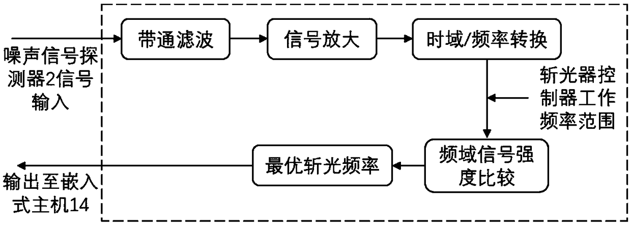
The invention relates to an photoacoustic spectroscopy detection device with a self-frequency- modulation noise reduction function. The photoacoustic spectroscopy detection device comprises a light source, a mechanical light chopper, a photochopper control module, a optical filter disc, an photoacoustic cell, a microphone, a phase-locking amplifier, a noise signal detector, an optimal photochopping frequency controller and an embedded host, wherein the photoacoustic spectroscopy detection device is provided with the noise signal detector and the optimal photochopping frequency controller; thenoise signal detector is arranged at the side wall of the photoacoustic cell and the installation direction of the noise signal detector is opposite to the installation direction of the microphone; the mechanical photochopper is controlled by the photochopping controller; the photochopping frequency of the photochopper control module is generated by the optimal photochopping frequency controller the processing on signals obtained by the noise signal detector and is transmitted to the photochopper control module through the embedded host.

Description

technical field [0001] The invention relates to a gas detection device. Background technique [0002] Gas detection technology has a wide range of applications in industrial production and daily life, such as leak detection of oil and gas pipelines, detection of dissolved gases in transformer oil in power systems, detection of exhaust gases from chemical companies, and detection of trace pollutant gases in the air, Exhaled gas detection in human diseases and medical diagnosis, etc. [0003] For example, in the power industry, it is used to detect electrical equipment failures, such as power transformers, SF6, fluorocarbon mixed gas and other gas-insulated electrical equipment failure decomposition gas; [0004] For oil-filled power transformers, the characteristic gases that need to be detected include H2, CO, CO2, CH4, C2H6, C2H4, C2H2, etc. At present, there are many detection methods for such gases; for example, patent 200910046340.7 mentions a system for on-line monito...

Claims


Application Information

Patent Timeline
IPC IPC(8): G01N21/17G01N21/01
CPCG01N21/01G01N21/1702
Inventor 李康张国强邱宗甲韩冬
Owner INST OF ELECTRICAL ENG CHINESE ACAD OF SCI
Learn More