A kind of optical imaging system and electronic equipment

An optical imaging system and optical axis technology, applied in optics, optical components, instruments, etc., can solve the problems that the optical system cannot meet the needs of the photography system, and achieve the effect of meeting application requirements, good processing technology, and excellent viewing angle

Active Publication Date: 2021-03-26
贵州旭业光电有限公司
View PDF5 Cites 0 Cited by
  • Summary
  • Abstract
  • Description
  • Claims
  • Application Information

AI Technical Summary

Problems solved by technology

[0003] Traditional lenses mounted on portable electronic products mostly use three-element or four-element lens structure, and the existing optical system can no longer meet the needs of higher-level photographic systems.

Method used


Image

  • A kind of optical imaging system and electronic equipment
  • A kind of optical imaging system and electronic equipment
  • A kind of optical imaging system and electronic equipment

Examples


Embodiment 1

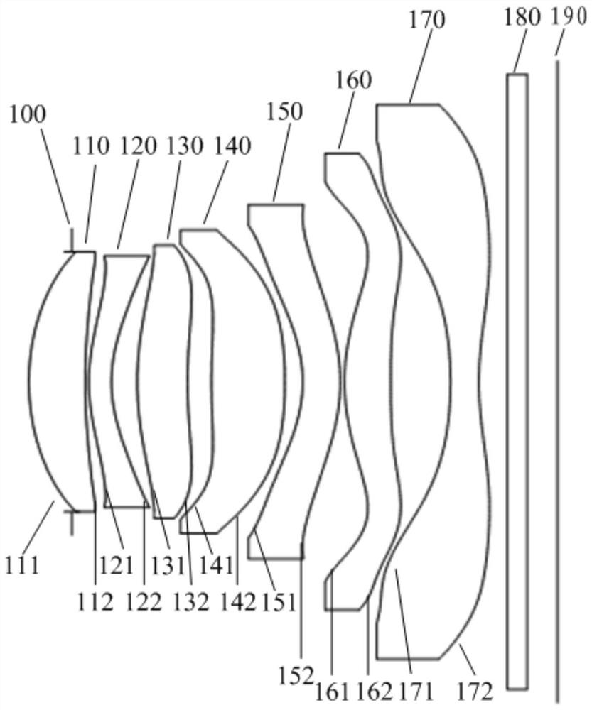
[0068] Please refer to figure 1, shows a schematic structural diagram of the optical imaging system of Embodiment 1. As can be seen from the figure, the optical imaging system of this embodiment includes a diaphragm 100, a first lens 110, a second lens 120, a third lens 130, a fourth lens 140, and a fifth lens 150 arranged in sequence along the optical axis from the object side to the image side , the sixth lens 160 and the seventh lens 170, each lens has an object side facing the object side and an image side facing the image side, and the object side and the image side of each lens are aspherical. The first lens 110 has positive refractive power and is made of plastic material. The object side 111 is convex at the near optical axis, and the image side 112 is concave at the near optical axis. The second lens 120 has negative refractive power and is made of plastic material. Its object side 121 is convex at the near optical axis, and its image side 122 is concave at the near ...

Embodiment 2

[0079] Please refer to Figure 4 , shows a schematic structural diagram of the optical imaging system of Embodiment 2. As can be seen from the figure, the optical imaging system of this embodiment includes a diaphragm 200, a first lens 210, a second lens 220, a third lens 230, a fourth lens 240, and a fifth lens 250 arranged in sequence along the optical axis from the object side to the image side , the sixth lens 260 and the seventh lens 270, each lens has an object side facing the object side and an image side facing the image side, and the object side and the image side of each lens are aspherical.

[0080] The first lens 210 has positive refractive power and is made of plastic material. The object side 211 is convex at the near optical axis, and the image side 212 is concave at the near optical axis. The second lens 220 has negative refractive power and is made of plastic material. The object side 221 is convex at the near optical axis, and the image side 222 is concave a...

Embodiment 3

[0089] Please refer to Figure 7 , shows a schematic structural view of the optical imaging system of Embodiment 3. As can be seen from the figure, the optical imaging system of this embodiment includes a diaphragm 300, a first lens 310, a second lens 320, a third lens 330, a fourth lens 340, and a fifth lens 350 arranged in sequence along the optical axis from the object side to the image side , the sixth lens 360 and the seventh lens 370, each lens has an object side facing the object side and an image side facing the image side, and the object side and the image side of each lens are aspherical.

[0090] The first lens 310 has positive refractive power and is made of plastic material. The object side 311 is convex at the near optical axis, and the image side 312 is concave at the near optical axis. The second lens 320 has negative refractive power and is made of plastic material. The object side 321 is convex at the near optical axis, and the image side 322 is concave at t...


PUM


Abstract

The invention discloses an optical imaging system which sequentially comprises a first lens, a second lens, a third lens, a fourth lens, a fifth lens, a sixth lens and a seventh lens from an object side to an image side. The first lens and the third lens have positive refraction power, the seventh lens has negative refraction power, the image side face, close to the optical axis, of the fourth lens is a convex surface, the image side face, close to the optical axis, of the fifth lens is a concave surface, and the image side face, close to the optical axis, of the seventh lens is a concave surface and is provided with at least one inflexion point. The lenses of the optical imaging system are combined by adopting a reasonable surface shape structure and an optimized range of optical parameters of the lens, the optical imaging system can have good imaging quality, and a large-image-surface imaging effect of the system can be achieved by reasonably allocating the thickness of the seventh lens and a view field angle of the optical imaging system. The optical imaging system can have the advantages of small size, large aperture, high pixel, high resolution, excellent view field angle andthe like and can provide good imaging quality. The invention also discloses an electronic device.

Description

technical field [0001] The invention relates to the technical field of optical imaging devices, in particular to an optical imaging system. The invention also relates to an electronic device. Background technique [0002] With the rapid upgrading of related consumer electronic products such as smart phones, portable computers and tablet devices, the market has higher and higher requirements for the quality of optical imaging lenses of electronic products. With the advancement of semiconductor manufacturing technology, the pixel size of photosensitive devices has been reduced. Correspondingly, optical imaging systems are gradually developing into the field of high pixels, so the requirements for its imaging quality are also increasing. [0003] Traditional lenses mounted on portable electronic products mostly use three-element or four-element lens structure, and the existing optical system can no longer meet the needs of higher-level photography systems. With the developmen...

Claims


Application Information

Patent Timeline
Patent Type & Authority Patents(China)
IPC IPC(8): G02B13/00
CPCG02B13/0045
Inventor 林肖怡袁正超王义龙章彬炜
Owner 贵州旭业光电有限公司
Why Eureka
Try Eureka