Current limiting equipment applicable to bidirectional flow direct current system distributed capacitance configuration

A DC system and equipment technology, applied in the direction of DC network circuit devices, circuit devices, emergency protection circuit devices, etc., can solve the problems of reducing the fault current level and the difficulty of breaking the DC fault current, so as to reduce the fault current level and enhance the fault. The effect of traversing ability and enhancing reliability

Inactive Publication Date: 2019-03-08
TIANJIN UNIV
View PDF4 Cites 2 Cited by
  • Summary
  • Abstract
  • Description
  • Claims
  • Application Information

AI Technical Summary

Problems solved by technology

[0003] Aiming at the problem of difficult breaking of the DC fault current in the DC power grid, and the DC system distributed capacitor configuration method itself is only applicable to the unidirectional power flow network, the present invention proposes a current limiting device suitable for the distributed capacitor configuration of the bidirectional power flow DC system, and gives The corresponding strategy of power flow reversing control, fault ride-through control and power supply recovery after fault clearing, while reducing the fault current level, ensures the bidirectional conduction capability of DC current during normal operation

Method used


Image

  • Current limiting equipment applicable to bidirectional flow direct current system distributed capacitance configuration
  • Current limiting equipment applicable to bidirectional flow direct current system distributed capacitance configuration
  • Current limiting equipment applicable to bidirectional flow direct current system distributed capacitance configuration

Examples


Embodiment Construction

[0016] The present invention will be described below in conjunction with the accompanying drawings and embodiments.

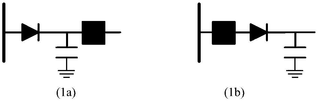
[0017] 1. For a DC system configured with distributed capacitors, if the power flow of the line is unidirectional, use the following at the head end of the DC line figure 1 (1a) or figure 1 The structure of (1b) is used to limit the fault current, and the box in the figure represents the DC circuit breaker.

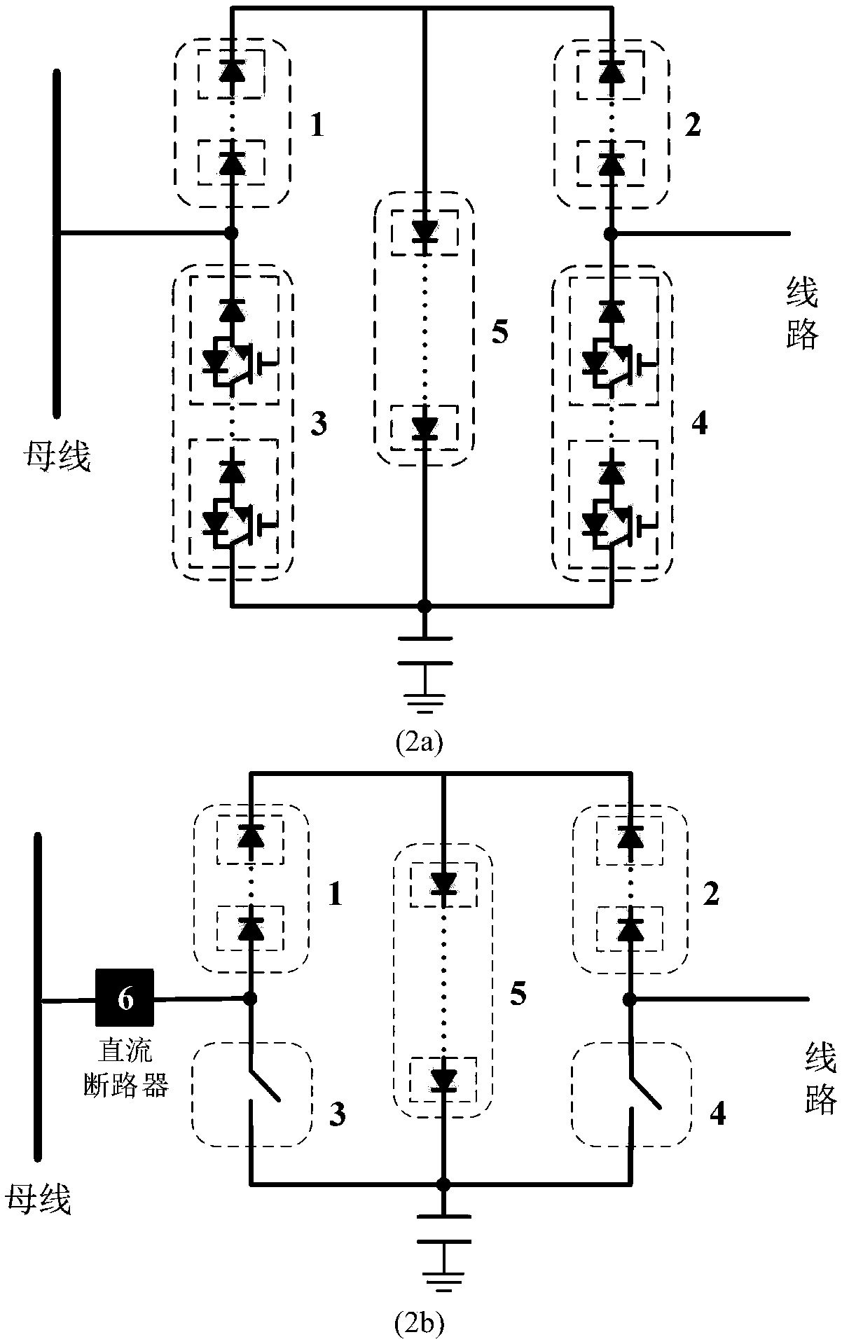
[0018] 2. A current-limiting device topology suitable for distributed capacitor configuration of bidirectional power flow DC system proposed by the present invention is as follows: figure 2 . 1 and 2 in the figure are diode bridge arms, 3 and 4 are switch bridge arms, 5 is an intermediate branch, and 6 in figure (2b) is a DC circuit breaker. Among them, Figure (2a) corresponds to Figure (1a); Figure (2b) corresponds to Figure (1b), and there is a DC circuit breaker between the H bridge and the busbar.

[0019] The bridge arm 1, the bridge arm 2 and th...


PUM


Abstract

The invention relates to current limiting equipment applicable to bidirectional flow direct current system distributed capacitance configuration. The current limiting equipment comprises an H bridge circuit composed of two diode bridge arms, two switch bridge arms and an intermediate branch circuit; the diode bridge arms and the intermediate branch circuit are respectively formed by connecting power diodes in series; the switch bridge arms are respectively formed by connecting switch elements in series, wherein the switch elements can be conducted unidirectionally and can be turned on and off,a collector, anode or drain electrode end of each switch bridge arm is called as a bridge arm positive pole, and a transmitter, cathode or source electrode end of each switch bridge arm is called asa bridge arm negative pole; the two diode bridge arms share the cathode; the negative pole of each switch bridge arm is connected with the anode of one of the diode bridge arms, and the switch bridgearms share the anode and are connected with an anode of a capacitor; and a cathode of the intermediate branch circuit is connected with a common point of the diode bridge arms, and an anode of the intermediate branch circuit is connected with a common point of the switch bridge arms. One of the common point of the diode bridge arms and the common point of the switch bridge arms is connected with adirect current bus, and the other one of the two common points is connected with a direct current circuit.

Description

technical field [0001] The invention relates to the field of DC system control and protection. In particular, it relates to a current-limiting device suitable for distributing capacitors in a bidirectional power flow DC system. Background technique [0002] DC power grid fault ride-through is an important topic of DC system protection and control. Due to the rapid rise of the DC fault current and the large peak current, it is difficult to interrupt the DC fault and cause great harm to the DC system and equipment. Therefore, it is of great significance for the fault ride-through and stable operation of the DC system to study the use of DC grid fault current limiting technology to reduce the fault current level and delay the fault development. At present, the research on the fault current limiting principle and equipment of the DC system starts from increasing the fault loop damping. Operational impact is the goal. Distributed capacitance configuration method in DC system,...

Claims


Application Information

Patent Timeline
Patent Type & Authority Applications(China)
IPC IPC(8): H02J1/00H02H7/26H02H3/06
CPCH02H3/06H02H7/268H02J1/00
Inventor 李斌叶仕磊李博通温伟杰
Owner TIANJIN UNIV
Why Eureka
Try Eureka