
Energy supply circuit of control IC in switch power supply

A switching power supply, energy supply technology, applied in electrical components, output power conversion devices, etc., can solve the problems of limiting the development of switching power supply, unable to reliably charge energy storage capacitors, etc., to improve safety, improve reliability, The effect of improving stability

Active Publication Date: 2019-03-08
MORNSUN GUANGZHOU SCI & TECH
View PDF3 Cites 0 Cited by
  • Summary
  • Abstract
  • Description
  • Claims
  • Application Information

AI Technical Summary

Problems solved by technology

Due to technical, cost and safety reasons, the existing constant-current high-voltage start-up chips cannot reliably charge the energy storage capacitors powered by large-capacity control ICs, which limits the development of switching power supplies. In the normal operation of the power supply, the energy storage capacitor powered by the control IC with a large capacity is used, and the control IC energy supply circuit that can use the existing constant current high voltage startup chip to charge the energy storage capacitor

Method used


Image

  • Energy supply circuit of control IC in switch power supply
  • Energy supply circuit of control IC in switch power supply

Examples


no. 1 example

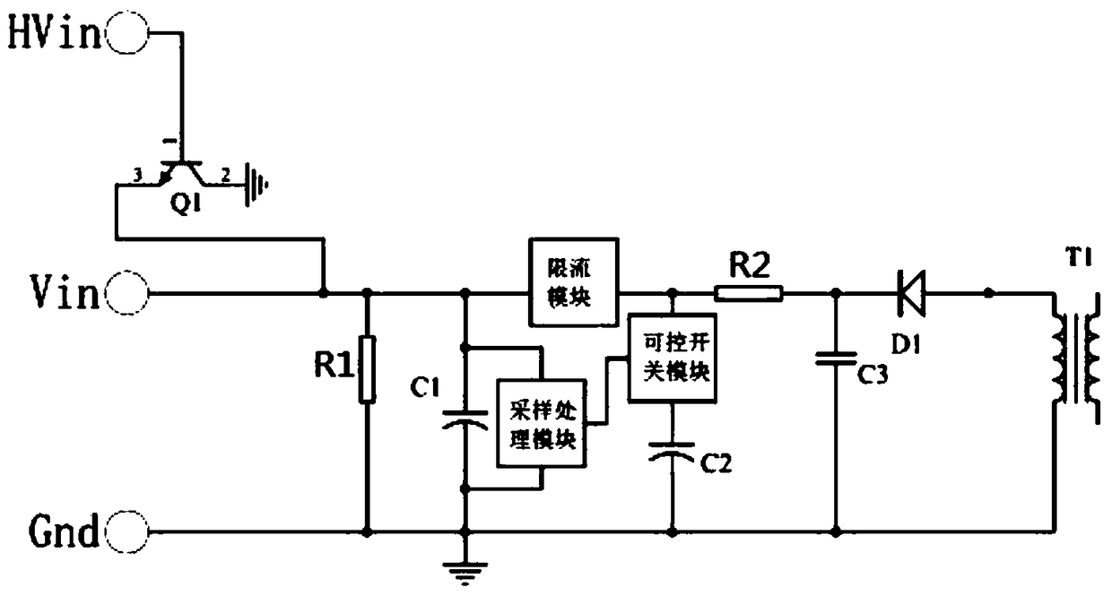
[0026] figure 1 It is the principle diagram of the first embodiment of the present invention, a switching power supply control IC energy supply circuit in the first embodiment of the present invention, including a constant current high voltage energy supply module, a first capacitor C1, a sampling processing module, a current limiting module, a controllable A switch module, a second capacitor C2, a first diode D1, a first resistor R1, a second resistor R2, a third capacitor C3 and a switching power supply transformer T1;

[0027] The connection relationship is: the constant-current high-voltage energy supply module is a triode, the base of the triode Q1 is connected to a high-voltage power supply as the high-voltage input end of the energy supply circuit, and the emitter of the triode Q1 is connected to one end of the resistor R1 , the positive pole of the capacitor C1, the first end of the current limiting module is connected to the input end of the external control IC, the s...

no. 2 example

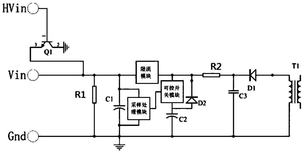
[0036] figure 2 It is the principle diagram of the second embodiment of the present invention, the main difference is that: the controllable switch module of this embodiment is unidirectional after conduction, and the second diode D2 is added; the connection relationship is: the controllable switch module The first end of the switch module is an input end, the second end of the controllable switch module is an output end, the anode of the diode D2 is connected to the second end of the controllable switch module, and the cathode of the diode D2 is connected to the second end of the controllable switch module. The first end of the controllable switch module is connected.

[0037] Compared with the first embodiment, the second embodiment adds a diode for automatic power supply, the threshold of the sampling processing module is changed from 3 to 2, and the threshold of "supply voltage" is deleted, that is, when the voltage across the capacitor C2 When the voltage is greater tha...


PUM


Abstract

The present invention provides an energy supply circuit of a control IC in a switch power supply. The circuit can improve the stability of the energy supply circuit of the control IC when the circuitis in normal working without affecting the startup of products. The circuit comprises a constant-current high-voltage energy supply module, a first power supply and energy storage module, a sampling and processing module, a current limiting module, a controllable switch module, a second power supply and energy storage module, a first diode and a switch power supply transformer. According to the circuit, by controlling the charging and discharging sequence of the first power supply and energy storage module and the second power supply and energy storage module, the control IC is supplied energycontinuously and steadily, and thus the stability of the switch power supply is effectively improved when the switch power supply is in operation.

Description

technical field [0001] The invention relates to the field of switching power supplies, in particular to an energy supply circuit of a control IC in a switching power supply. Background technique [0002] Switching power supply is a kind of power supply that controls the turn-on and turn-off time ratio of the switch tube, and then outputs and maintains a stable output voltage by the energy storage element. Switching power supply is widely used in almost all Among electronic equipment, high-efficiency switching power supplies are not only safe and reliable, but also more energy-saving and environmentally friendly, and are greatly loved by the market and customers. [0003] Transformer is the most commonly used method of energy storage and transmission for high-power switching power supplies. The auxiliary winding in the transformer is used as the power supply source for switching power supply control ICs. This is also the most commonly used power supply method for controlling ...

Claims


Application Information

Patent Timeline
Patent Type & Authority Applications(China)
IPC IPC(8): H02M1/00
CPCH02M1/00H02M1/0006
Inventor 李钱挺陈宁翁斌
Owner MORNSUN GUANGZHOU SCI & TECH
Learn More