
Water cutting machine recycling system

A technology of water cutting machine and cutting machine, which is applied in the direction of abrasive jet machine tool, used abrasive processing device, fixed filter element filter, etc. It can solve the problems of high equipment cost, poor processing accuracy, nozzle wear and cutting cost, etc. Achieve the effects of improving processing efficiency, reducing production costs, and improving management efficiency

Pending Publication Date: 2021-11-19
李凤伶
View PDF0 Cites 0 Cited by
  • Summary
  • Abstract
  • Description
  • Claims
  • Application Information

AI Technical Summary

Problems solved by technology

[0002] In order to improve efficiency, people apply high pressure to water and spray it from a nozzle with a smaller diameter, creating a processing method that uses high-pressure water jet impact to remove materials. This processing method has the advantages of high precision and wide application range. However, the abrasive water jet equipment in the water cutting machine has the problems of nozzle wear and high cutting cost. The equipment cost of high pressure water jet is higher than other cutting methods. Compared with laser cutting under some working conditions, the feed rate is low and the processing accuracy is poor. Insufficient, and its high processing costs have affected the choice of many factories. At the same time, the high-pressure water cutting machine consumes a lot of water. On the one hand, it accelerates the consumption of water resources, and on the other hand, it produces more polluted water. Therefore, the water cutting machine Recycling of production wastewater is crucial

Method used


Image

  • Water cutting machine recycling system
  • Water cutting machine recycling system
  • Water cutting machine recycling system

Examples


Embodiment Construction

[0023] The following are specific embodiments of the present invention and in conjunction with the accompanying drawings, the technical solutions of the present invention are further described, but the present invention is not limited to these embodiments.

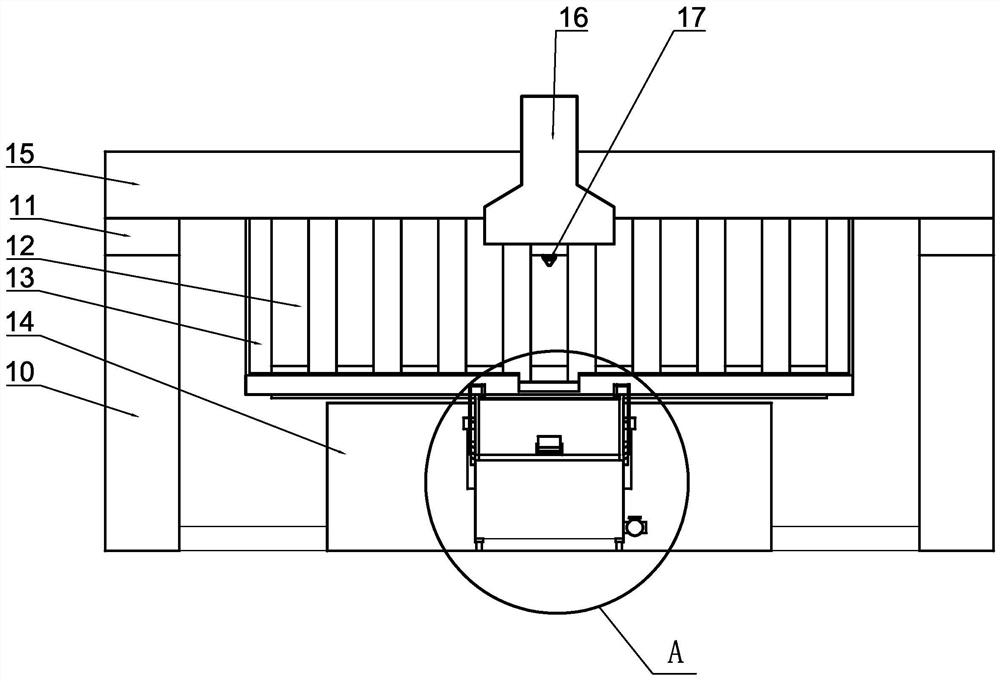
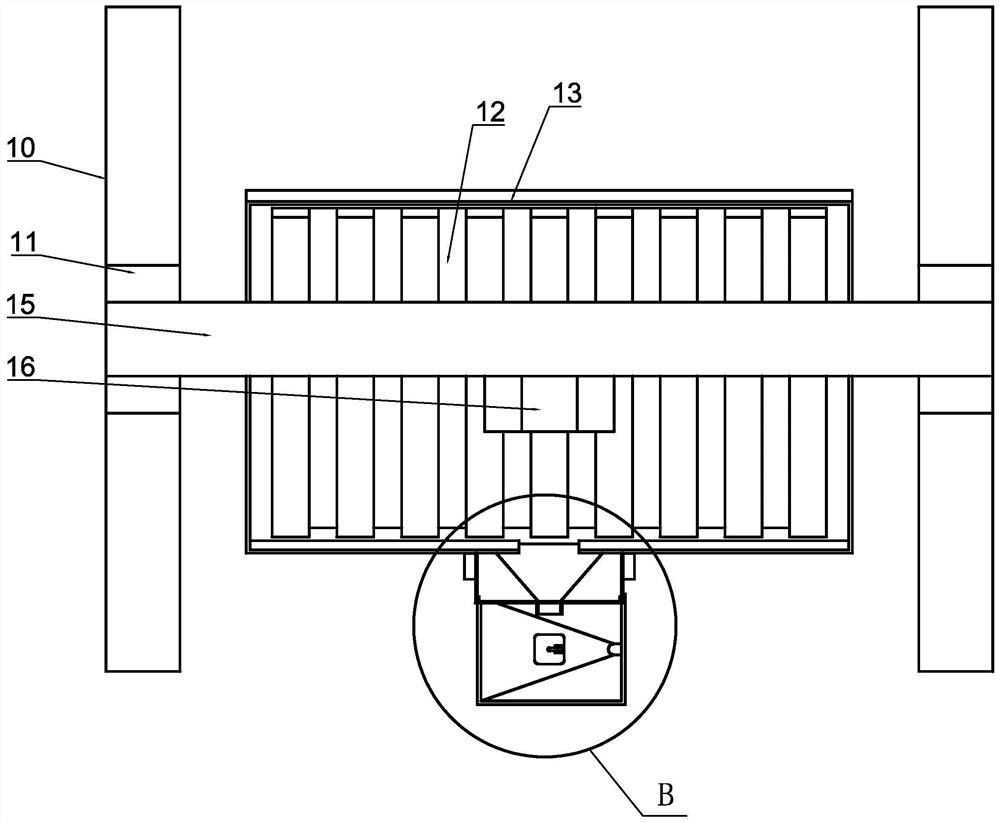
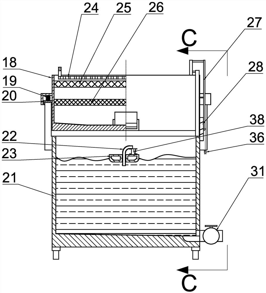
[0024] Such as figure 1 and figure 2 As shown, a recycling system of a water jetting machine includes a base 10, and two sliders 11 are arranged on the upper side of the base 10 to slide forward and backward symmetrically. A cutting machine 16 is provided for sliding up and down, a high-pressure water cutting head 17 is provided at the lower end of the cutting machine 16, a hydraulic table 14 is fixedly provided on the base 10, and a storage table 12 is fixedly provided on the upper side wall of the hydraulic table 14, and the storage table 12 is fixed. A water guide groove inclined to the front side is provided, a sump 13 is fixedly arranged on the outer ring of the storage table 12, and a sedimentation device is provid...


PUM


Abstract

The invention belongs to the related field of cutting machines, and relates to a water cutting machine recycling system which comprises a base. Two sliding blocks are arranged on the upper side of the base in left-right symmetrical and front-back sliding modes, a cross beam is fixedly arranged on the left sliding block and the right sliding block, a cutting machine is arranged on the cross beam in a left-right sliding mode, a high-pressure water cutting head is arranged at the lower end of the cutting machine, a hydraulic table is fixedly arranged on the base, and a storage table is fixedly arranged on the upper side wall of the hydraulic table. After the high-pressure water cutting machine completes granite cutting, waste liquid and waste residues generated by cutting are collected, the waste liquid is filtered, the waste residues are screened, the screened granite waste residues are ground into quartz sand for waste residue recovery, after the waste liquid is subjected to solid particle precipitation, supernatant water is taken for reuse, the quantity of production garbage is reduced, the production cost is reduced, and the problem of waste water recovery after granite cutting is solved.

Description

technical field [0001] The invention belongs to the related field of cutting machines, in particular to a recycling system of water cutting machines. Background technique [0002] In order to improve efficiency, people apply high pressure to water and spray it from a nozzle with a smaller diameter, creating a processing method that uses high-pressure water jet impact to remove materials. This processing method has the advantages of high precision and wide application range. However, the abrasive water jet equipment in the water cutting machine has the problems of nozzle wear and high cutting cost. The equipment cost of high pressure water jet is higher than other cutting methods. Compared with laser cutting under some working conditions, the feed rate is low and the processing accuracy is poor. Insufficient, and its high processing costs have affected the choice of many factories. At the same time, the high-pressure water cutting machine consumes a lot of water. On the one h...

Claims


Application Information

Patent Timeline
Patent Type & Authority Applications(China)
IPC IPC(8): B24C1/04B24C3/04B24C9/00B01D29/03B01D29/58
CPCB24C1/045B24C3/04B24C9/00B24C9/006B01D29/03B01D29/58Y02P70/10
Inventor 李凤伶
Owner 李凤伶
Learn More