Electric furnace with good cooling effect
A technology of heat dissipation effect and electric furnace, applied in electrical components, induction heating, ohmic resistance heating parts and other directions, can solve the problems of single heat dissipation circuit, affecting heat dissipation effect, charring of countertops, etc., to reduce heat dissipation noise, convenient structure design, The effect of improving the heat dissipation effect
- Summary
- Abstract
- Description
- Claims
- Application Information
AI Technical Summary
Problems solved by technology
Method used
Image
Examples
no. 1 example
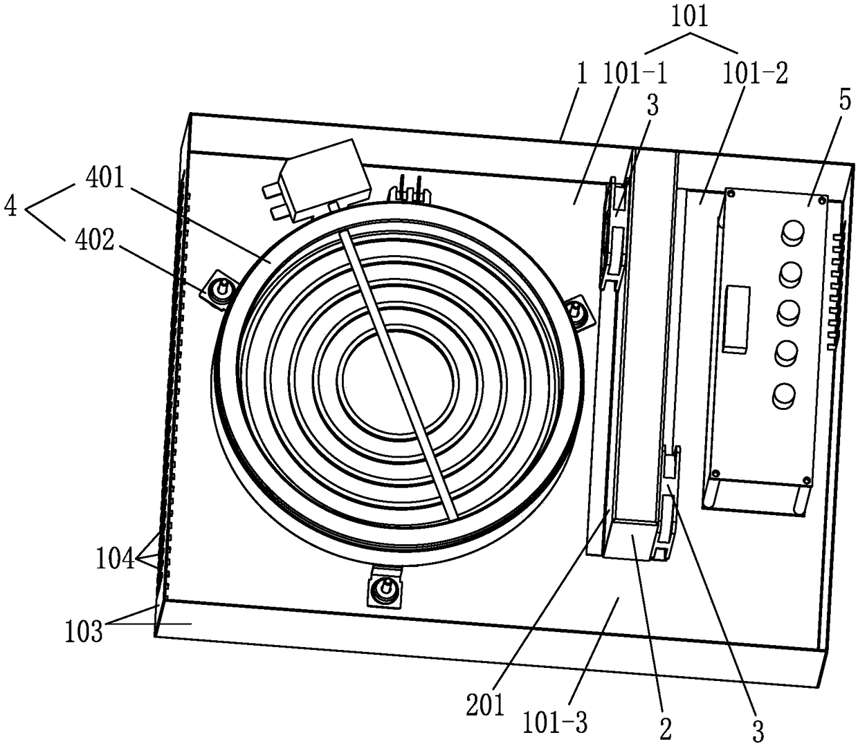
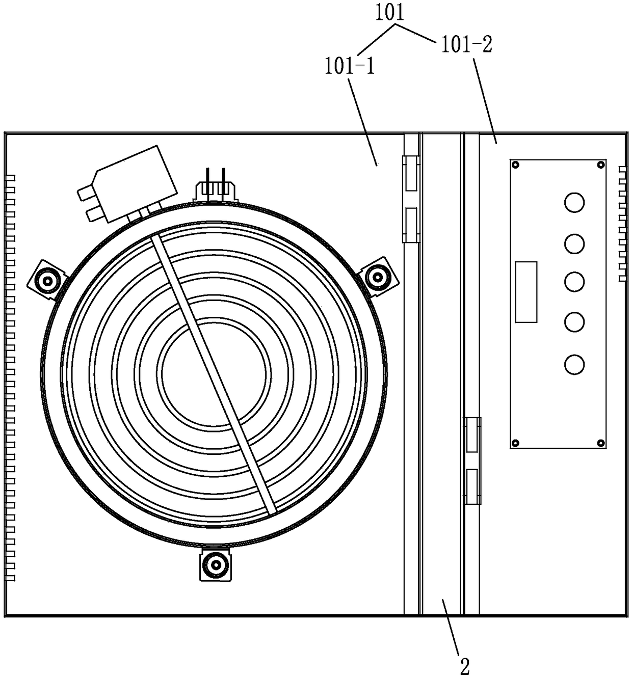
[0038] The first embodiment: such as Figure 1 to Figure 2 Shown: an electric furnace with good heat dissipation effect, including a furnace body 1, a furnace cavity 101 is provided in the furnace body 1, and is characterized in that at least one air trough 2 is installed in the furnace body 1, and the air trough 2 connects the furnace cavity 101 is divided into at least two installation cavities 101-1 and 101-2. The bottom of the air channel 2 corresponds to the bottom plate 105 of the furnace body 1 with a first air port 102 communicating with the air channel 2, and a heat dissipation fan 3 is installed on the air channel 2. Through the convection guidance of the cooling fan 3, the first tuyere 102 is connected to the installation cavity 101-1, 101-2.
[0039] In the electric furnace with this structure, the air duct 2 is optimized and utilized, and an independent air duct is formed inside the air duct 2, and the air in the installation cavity 101-1, 101-2 is connected with the...
no. 2 example
[0050] Second embodiment: The air channel 2 divides the furnace cavity into two independent installation cavities 101-1, 101-2; the furnace cavity 101 is partitioned by the air channel 2, that is, the air channel 2 is used to divide the furnace cavity 101 into two The installation cavities 101-1, 101-2, the two installation cavities 101-1, 101-2 can be independent cavities, such as image 3 As shown, separated by the air duct 2, the temperature of the two installation cavities 101-1, 101-2 does not interfere and transfer, so as to prevent the heat transfer from the high temperature area to the low temperature area, and make one of the installation cavities 101-1 work at a safe temperature It is not affected by another adjacent installation cavity 101-2, so that each independent installation cavity 101-1, 101-2 can be equipped with suitable cooling fans and cooling air according to the shape and characteristics of the components installed in the cavity. This way, the heat dissipa...
no. 3 example
[0051] The third embodiment: such as Figure 4 As shown, two air guide plates 6 are provided in the installation cavities 101-1 and 101-2. The air guide cavity 7 is formed between the two air guide plates 6 and the heating assembly 4 is arranged in the air guide cavity 7 at one end of the air guide cavity 7 It is connected to the heat dissipation fan 3; the air guide cavity 7 can smoothly and quickly lead out the hot air in the heating assembly 4 along between the two air guide plates 6.
PUM
 Abstract
Description
Claims
Application Information
 - R&D
- Intellectual Property
- Life Sciences
- Materials
- Tech Scout
- Unparalleled Data Quality
- Higher Quality Content
- 60% Fewer Hallucinations
Browse by: Latest US Patents, China's latest patents, Technical Efficacy Thesaurus, Application Domain, Technology Topic, Popular Technical Reports.
© 2025 PatSnap. All rights reserved.Legal|Privacy policy|Modern Slavery Act Transparency Statement|Sitemap|About US| Contact US: help@patsnap.com


