Device special for drainage

A special device and drainage tube technology, applied in the field of medical equipment, can solve the problems of unsatisfactory drainage effect, poor drainage patency of drainage tube, poor safety, etc.

Inactive Publication Date: 2019-03-12
徐州智编信息科技有限公司
View PDF0 Cites 2 Cited by
  • Summary
  • Abstract
  • Description
  • Claims
  • Application Information

AI Technical Summary

Problems solved by technology

[0003] In order to solve this situation, a stool drainage device has appeared, but the existing stool drainage device has the following disadvantages: 1. The structure is complicated and the operation is inconvenient; 2. The safety is poor, and the intestinal mucosa of the patient is easily damaged during the intubation process. ; 3. The fixation effect in the patient's body is not good, and it is easy to fall off when the patient turns over or moves slightly; 4. The drainage patency of the drainage tube is not good, and the drainage effect is not ideal

Method used


Image

  • Device special for drainage

Examples


Embodiment Construction

[0019] The present invention will be further described below in conjunction with accompanying drawing.

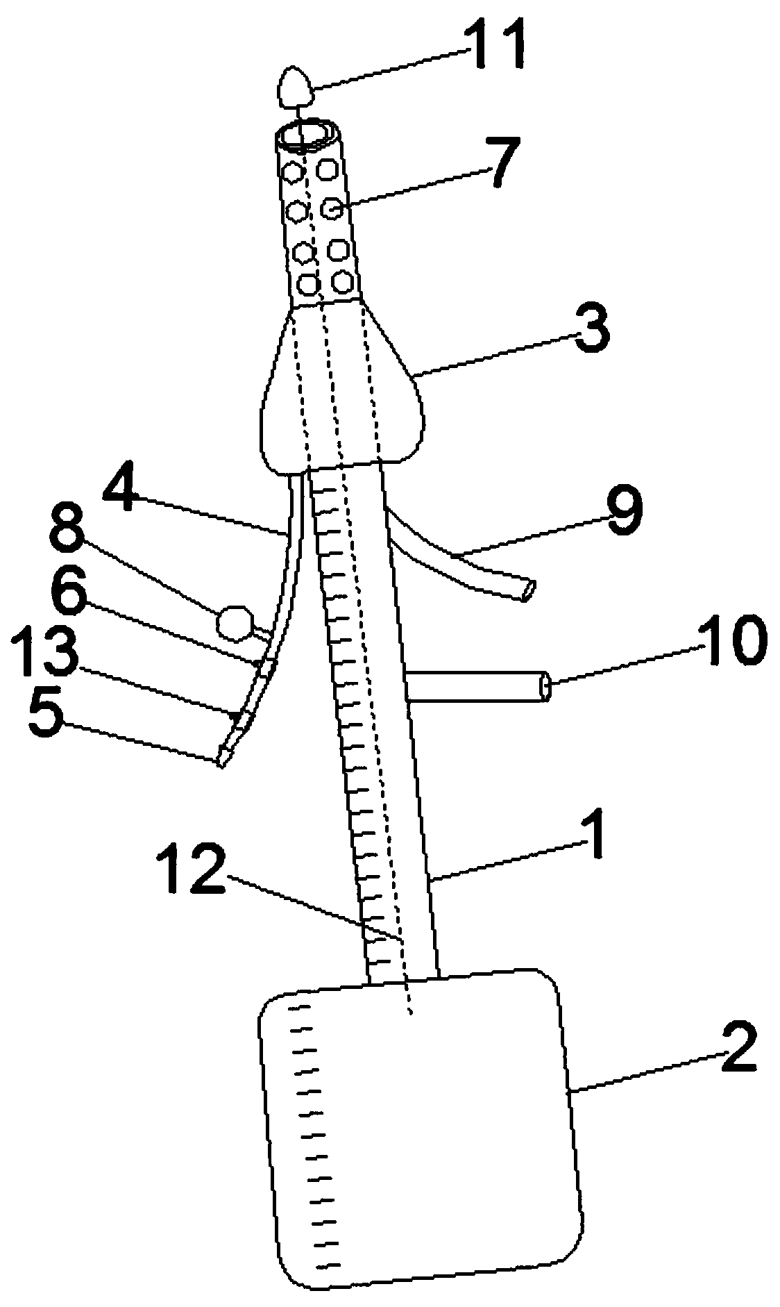
[0020] Such as figure 1 As shown, a special device for drainage includes a drainage tube 1, an annular air bag 3 and a plug 11 that slides and fits with the inner wall of the drainage tube 1; the upper end of the drainage tube 1 is used as the liquid inlet end, and the lower end of the drainage tube 1 is used as the outlet. The liquid end is detachably connected with a drainage bag 2 through a connecting joint;

[0021] The airbag 3 is fixedly sleeved on the outside of the drainage tube 1, and is arranged close to the liquid inlet end; the airbag 3 is connected with an inflation pipeline 4 communicating with its inner cavity; the inflation pipeline 4 is connected with an inflation nozzle at the inlet end 5. The inflation pipeline 4 is also connected with a pressure regulating valve 6 near the intake end;

[0022] In order to improve the patency of drainage, a section of t...


PUM


Abstract

The invention discloses a device special for drainage. The device comprises a drainage pipe, an annular gasbag and a blocking head which is in sliding fit with the inner side wall of the drainage pipe; the upper end of the drainage pipe serves as a liquid inlet end, and the lower end of the drainage pipe serves as a liquid outlet end and is detachably connected with a drainage bag through a connecting joint; the gasbag fixedly sleeves the outer side of the drainage pipe and is arranged close to the liquid inlet end; an inflation pipeline communicated with an inner cavity of the gasbag is connected to the gasbag; an air inflation nozzle is connected to the inflation pipeline at the air inlet end, and a pressure adjusting valve is further connected to the portion, close to the air inlet end,of the air inflation pipeline; multiple drainage holes are formed in the section, between the air inlet end and the gasbag, of the drainage pipe in the length direction of the drainage pipe; the blocking head is in a shape of a bullet, and is arranged at the inner side of the liquid inlet end of the drainage pipe and connected with a silica gel strip, and the free end of the silica gel strip penetrates through the drainage pipe and penetrates out of the liquid outlet end. The device has a good fixing effect in the body of a patient, and does not easily fall off; meanwhile, the drainage smoothness of the device is good, and the drainage effect is ideal.

Description

technical field [0001] The invention belongs to the technical field of medical devices, in particular to a special device for drainage. Background technique [0002] Some patients will have fecal incontinence during the onset of the disease. For such patients, nurses and family members mostly need to frequently clean the perianal skin of the patient, and replace toilet paper, diapers, bed sheets, etc. to solve the nursing problem of incontinence. This method is not only for nurses and The labor intensity of the family members is very high, and the nursing cost is high. In addition, the perianal skin of the patient is stimulated by excrement for a long time, which is prone to complications such as flushing, damage, bleeding, pain, eczema, ulceration and even pressure sores. [0003] In order to solve this situation, a stool drainage device has appeared, but the existing stool drainage device has the following disadvantages: 1. The structure is complicated and the operation is...

Claims


Application Information

Patent Timeline
Patent Type & Authority Applications(China)
IPC IPC(8): A61M25/10A61M1/00A61M3/02
CPCA61M3/0295A61M25/007A61M25/0075A61M25/10A61M2025/0002A61M2205/3331A61M2210/1064A61M1/84A61M2210/005
Inventor 贺子宇
Owner 徐州智编信息科技有限公司
Why Eureka
Try Eureka