Device for small hole die cutting

A technology of die-cutting and negative pressure device, which is applied in metal processing and other directions, can solve problems such as affecting processing efficiency, easy bonding and staying, and achieve the effect of improving die-cutting processing efficiency.

Active Publication Date: 2019-03-12
络派科技(深圳)有限公司
View PDF5 Cites 4 Cited by
  • Summary
  • Abstract
  • Description
  • Claims
  • Application Information

AI Technical Summary

Problems solved by technology

[0004] Since the single-layer material used for compounding is usually a light, thin, elastic and easily deformable material, and materials such as double-sided adhesive tape also have a certain viscosity, therefore, when the diameter of the small hole 100 to be processed is less than 5mm, On the one hand, the excised waste at the position of the small hole 100 is easy to stick to the body of the soft and thin material 300, and is also easy to stick and stay on the cutter. Therefore, it is necessary to design a complicated waste removal device such as a blower to remove the waste. Continue processing, which greatly affects the processing efficiency

Method used


Image

  • Device for small hole die cutting
  • Device for small hole die cutting
  • Device for small hole die cutting

Examples


Embodiment Construction

[0024] In order to have a clearer understanding of the technical features, purposes and effects of the present invention, the specific implementation manners of the present invention will now be described with reference to the accompanying drawings. Wherein, the same parts adopt the same reference numerals.

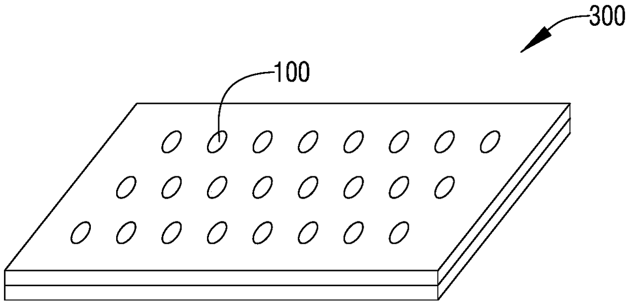
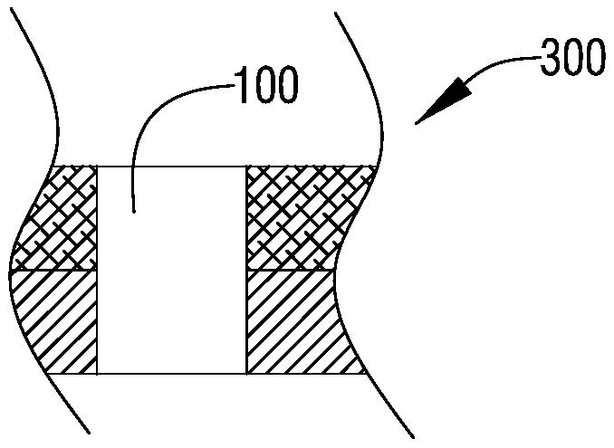
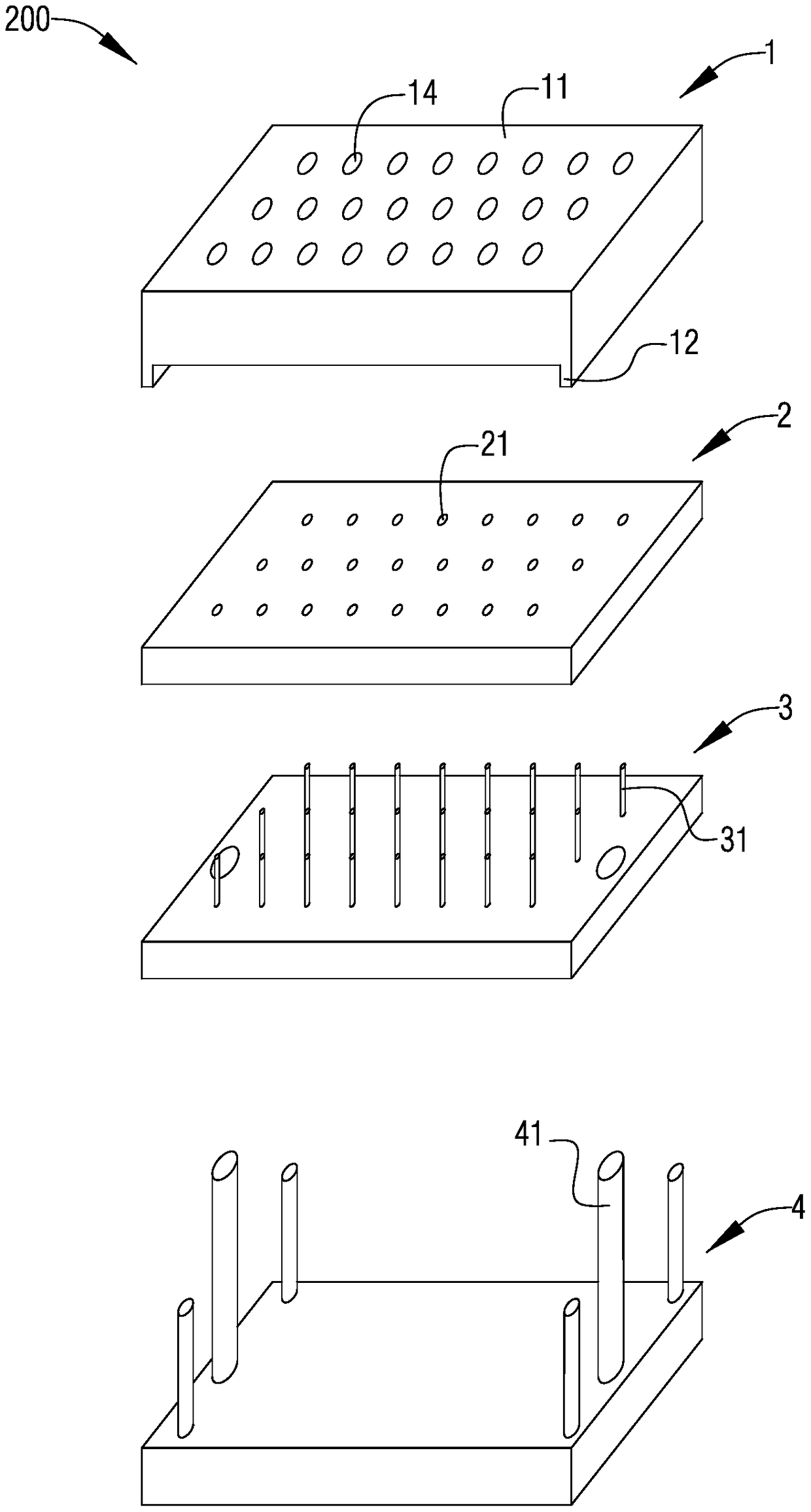
[0025] figure 1 It is a schematic diagram of the structural principle of a soft and thin material that completes small hole processing; figure 2 for figure 1 Schematic diagram of the partial cross-sectional structure principle; image 3 It is a schematic diagram of the three-dimensional decomposition structure principle of the device for small hole die-cutting according to a specific embodiment of the present invention; Figure 4 for image 3 Schematic diagram of the three-dimensional structure of the knife plate; Figure 5 for image 3 Schematic cross-sectional structural diagram of the principle of use of the device for small hole die-cutting; Figure 6 for Fi...


PUM


Abstract

A device for small hole die cutting comprises an upper tool plate, a lower tool plate and an ejector plate. The upper tool plate comprises a body part, a limiting part and a tool bit part. The limiting part and the tool bit part 13 are equal in height. The body part and the tool bit part are provided with penetrating waste discharging holes, wherein the waste discharging holes are the same with small holes in diameter. The lower tool plate is provided with guiding holes, and the diameter of the guiding holes is smaller than the diameter of the small holes. The ejector plate is provided with ejector columns, the diameter of the ejector columns is smaller than or equal to the diameter of the guiding holes, and the height of the ejector columns is larger than the thickness of the guiding holes. The tool bit part, the guiding holes and the ejector columns are coaxially arranged, and the lower tool plate and the ejector plate can be in sliding connection. According to the provided device for small hole die cutting, through the arrangement of the movable lower tool plate and matched ejector rods, the cut waste can be effectively separated, and the small hole die cutting machining efficiency can be greatly improved.

Description

technical field [0001] The invention relates to the technical field of die-cutting, in particular to a device for die-cutting small holes. Background technique [0002] Die-cutting single-layer soft and thin materials or compounding multi-layer soft and thin materials is a common die-cutting process. For example, when processing speaker mesh parts for mobile phones, the bottom paper and both sides The glue is compounded, and then the compounded two-layer structure is die-cut and punched, and then the speaker mesh is compounded on the double-sided glue of the two-layer structure that has completed the hole forming process, and the blank part preparation of the speaker mesh part is completed. [0003] figure 1 It is a schematic diagram of the structural principle of a soft and thin material that completes small hole processing; figure 2 for figure 1 Schematic diagram of the partial cross-sectional structure. see figure 1 and figure 2 As shown, in order to improve the u...

Claims


Application Information

Patent Timeline
Patent Type & Authority Applications(China)
IPC IPC(8): B26F1/02B26D7/18
CPCB26D7/1818B26F1/02
Inventor 白海光陈海兰邢金明
Owner 络派科技(深圳)有限公司
Why Eureka
Try Eureka