Die cutting hob assembly

A hob and die-cutting technology, which is applied in metal processing and other directions, can solve the problem of converging and shrinking the outer side of the final product into a pointed protrusion, and achieve the effect of improving die-cutting efficiency and good cutting effect

Active Publication Date: 2021-07-30
浙江美生日化用品有限公司
View PDF14 Cites 0 Cited by
  • Summary
  • Abstract
  • Description
  • Claims
  • Application Information

AI Technical Summary

Problems solved by technology

[0004] In view of the above-mentioned related technologies, the inventor believes that since the shape of the cut packaging unit is rectangular, when the inner packaged items are heated and shrunk, the heat-shrinkable film shrinks synchronously. Due to the different distances to be shrunk, it is inevitable that the final product The outer side converges and shrinks into a pointed protrusion, which is very difficult to handle

Method used


Image

  • Die cutting hob assembly
  • Die cutting hob assembly
  • Die cutting hob assembly

Examples


Embodiment 1

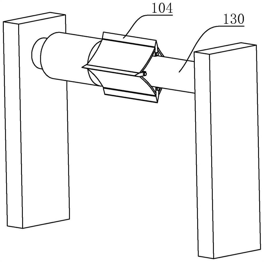
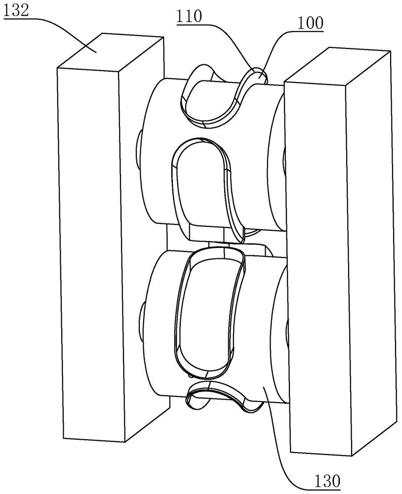
[0062] Embodiment 1 of the present application discloses a die-cutting hob assembly, referring to image 3 , Figure 4 , comprising a roller 130, at least one cutter body 100 is arranged on the roller 130, and the cutter body 100 is a closed ring shape. In this embodiment, the shape of the cutter body 100 and the object are arc-shaped segments at both ends and two segments in the middle Parallel segments, similar to the shape of a runway. The peripheral edge of the cutter body 100 is adapted to the peripheral edge of the article. In this embodiment, the two edges are equidistantly arranged. The cutter body 100 is used for die-cutting and is provided with a cutting ring edge 110, and the cutting ring edge 110 is located on the same virtual curved surface. The cutting edge 110 of the cutter body 100 has the same cross-sectional area from one side to the other side, and the thickness of the cutter body 100 along the extending direction thereof is uniform.

[0063] refer to F...

Embodiment 2

[0068] The difference from Example 1 is that, referring to Figure 6 , Figure 7 , the cutter body 100 is arranged in multiple groups along the axial direction, and a heat conduction base 140 is provided on the circumferential side wall of the roller 130. Correspondingly, the heat conduction base 140 is installed by bolts, which can be easily replaced, and can also be welded on the roller 130, and the entire roller 130 will be replaced at that time.

[0069] refer to Figure 7 , Figure 8 , the heat conduction base 140 is provided with a socket 150 for inserting and fixing the side of the cutter body 100 away from the cutting ring edge 110. The socket 150 is two clips 151 arranged side by side, and there are multiple sockets 150. The circumferential direction of the cutter body 100 is welded on the heat conduction base 140, and the side of the cutter body 100 away from the cutting ring edge 110 will be embedded between the two clips 151, and the two clips 151 are fixed and ...

Embodiment 3

[0074] The difference from Example 1 is that, referring to Figure 10 , Figure 11 , the cutter body 100 is arranged in multiple sets along the axial direction, and the heat conduction base 140 is not only in an arc shape adapted to the roller shaft 130, but also in the radial direction along the roller shaft 130, the heating element is in a ring shape adapted to the cutter body 100. In the embodiment, the heating element is a heating pipe 155 , and the heating pipe 155 coincides with the cutter body 100 on the projection along the radial direction of the roller 130 . The heat conduction base 140 has a slot 157 for inserting the heating tube 155, and the upper side of the heating tube 155 has a receiving groove 156 for inserting the cutter body 100 away from the cutting ring edge 110. When the cutter body 100 is inserted into the socket 150 When it is inside, the cutter body 100 will be inserted into the accommodating groove 156 , so that the cutter body 100 is in contact wit...


PUM


Abstract

The invention relates to the technical field of packaging devices, in particular to a die cutting hob assembly which comprises a rolling shaft, at least one cutter body is arranged on the rolling shaft, the cutter body is in a closed ring shape, the perimeter edge of the cutter body is matched with the perimeter edge of an object, and cutting ring blades are arranged on the side, used for die cutting, of the cutter body. The cutting ring blades are located on the same virtual arc-shaped face, and the side, away from the cutting ring blades, of the cutter body is arranged on the side wall of the rolling shaft. The die cutting hob assembly further comprises a heating piece, and the heating piece is arranged on the rolling shaft and is used for heating the cutter body. The die cutting hob assembly has the following effects that in the subsequent thermal shrinkage process, a thermal shrinkage film needs to be shrunk to the edge of an object by the same distance, and sharp protrusions on the edge of a finished product can hardly appear.

Description

technical field [0001] The present application relates to the technical field of packaging devices, in particular to a die-cutting hob assembly. Background technique [0002] At present, in the category of daily necessities, such as compressed towels, soap, laundry blocks, effervescent tablets for washing machine slots or dishwashing blocks, packaging is required before sales. The existing packaging method is to place the articles 101 in the middle of the heat-shrinkable film 102 at intervals in sequence, and the heat-shrinkable film 102 is cylindrical, and through such as figure 1 The die-cutting hob shown cuts the heat-shrinkable film 102 into individual multiple pieces such as figure 2 As shown in the packaging units 103 , each packaging unit 103 contains an article 101 , and then the packaging unit 103 is heated in a subsequent process. At this time, the heat shrinkable film 102 shrinks and wraps the article 101 . [0003] Existing die-cutting hob comprises a roller 1...

Claims


Application Information

Patent Timeline
Patent Type & Authority Applications(China)
IPC IPC(8): B26F1/42B26F1/44B26D7/10
CPCB26F1/42B26F1/44B26D7/10B26F2001/4472B26F2001/4481
Inventor 马小明郑鹏波张栋栋
Owner 浙江美生日化用品有限公司
Why Eureka
Try Eureka