
Die-cutting machine capable of efficiently manufacturing base table paper and using method of die-cutting machine

A high-efficiency, die-cutting machine technology, applied in metal processing and other directions, can solve the problems of low efficiency, inconvenient adjustment, difficulty in adapting to different specifications of paper, etc., and achieve the effect of improving die-cutting efficiency

Pending Publication Date: 2021-10-15
宁夏金世纪包装印刷有限公司
View PDF1 Cites 0 Cited by
  • Summary
  • Abstract
  • Description
  • Claims
  • Application Information

AI Technical Summary

Problems solved by technology

[0008] The purpose of the present invention is to provide a die-cutting machine capable of efficiently making bottom table paper and its use method. By setting a plurality of positioning components, a plurality of die-cutting components and a plurality of T-shaped air ducts, the die-cutting machine can Die-cutting multiple tables at the same time can greatly improve the efficiency of die-cutting, and the adjustable design of positioning components and die-cutting components makes the equipment adaptable to the needs of different widths and thicknesses of table paper, which solves the existing problem The die-cutting machine for making bottom table paper is inefficient and inconvenient to adjust, making it difficult to adapt to different specifications of paper

Method used


Image

  • Die-cutting machine capable of efficiently manufacturing base table paper and using method of die-cutting machine
  • Die-cutting machine capable of efficiently manufacturing base table paper and using method of die-cutting machine
  • Die-cutting machine capable of efficiently manufacturing base table paper and using method of die-cutting machine

Examples


Embodiment Construction

[0041] The technical solutions in the embodiments of the present invention will be apparent from the drawings in the embodiment of the present invention.

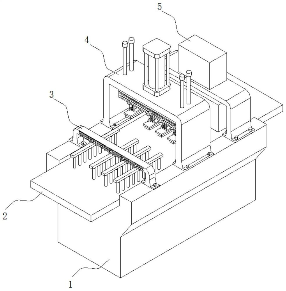
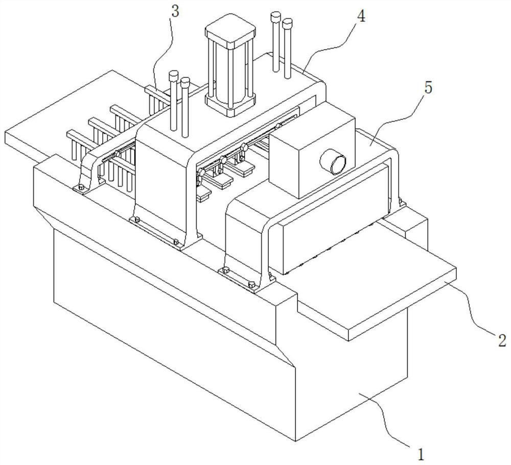
[0042] See Figure 1-2 As shown, the present invention is a die cutter that can make the base paper, including the frame 1, the positioning mechanism 3, the die cutting mechanism 4, and the exhausting mechanism 5, and the top groove of the rack 1 is provided. Table 2, the top of the frame 1 is provided with a positioning mechanism 3, a die cutting mechanism 4, and a waste mechanism 5 in the transfer direction of the frame.

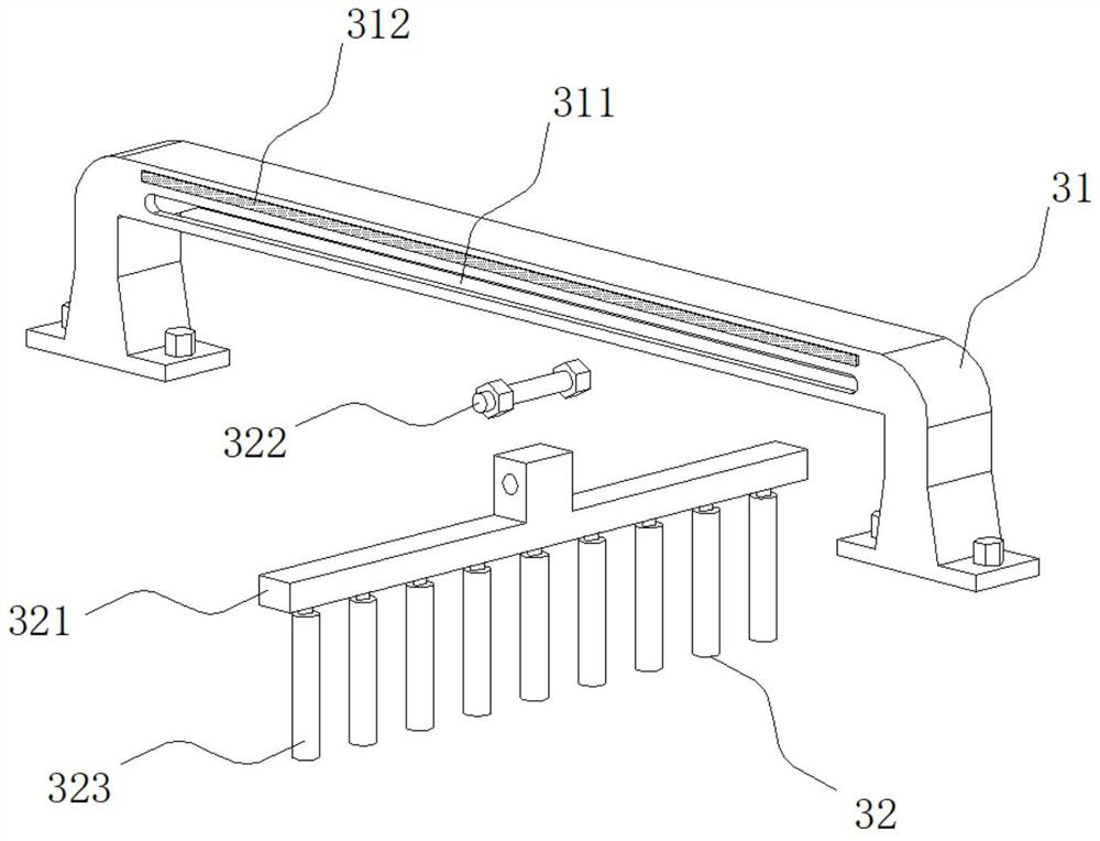
[0043] In which image 3 As shown, the positioning mechanism 3 includes positioning the gantry 31 and the positioning assembly 32, positioning the gantry 31 on the frame 1, and four positioning assemblies 32 are positioned on the beam of the gantry 31, and the positioning assembly 32 includes a T-rack 321. The first bolt 322 and the roller 323, the top of the T-rack 321 slides in conjunction with the beam bot...


PUM


Abstract

The invention discloses a die-cutting machine capable of efficiently manufacturing base table paper and a using method of the die-cutting machine, and relates to the technical field of paper production. The die-cutting machine comprises a rack, a positioning mechanism, a die cutting mechanism and a waste cleaning mechanism, a workbench is arranged in a groove in the top of the rack, and the positioning mechanism, the die cutting mechanism and the waste cleaning mechanism are arranged on the top of the rack in the table paper conveying direction; the positioning mechanism comprises a positioning portal frame and a positioning assembly; and the die cutting mechanism comprises a die cutting portal frame, an air cylinder, a lifting frame and a die cutting assembly. Through the arrangement of the multiple positioning assemblies, the multiple die cutting assemblies and the multiple T-shaped air pipes, the die cutting machine can conduct die cutting on multiple pieces of table paper at the same time, so that the die cutting efficiency can be greatly improved, the positioning assemblies and the die cutting assemblies are designed in an adjustable mode, the die-cutting machine can meet the use requirements of the table paper with different widths and thicknesses, and the problems that an existing die-cutting machine for manufacturing base table paper is low in efficiency, inconvenient to adjust and difficult to adapt to paper of different specifications are solved.

Description

Technical field [0001] The present invention belongs to the field of paper production, and in particular, the present invention relates to a die cutting machine that can be made of base paper and its use. Background technique [0002] Tape paper is a design drawings labeled in the printing mills. Tape paper specifies the arrangements of various parts of the layout, which is the basis for the imposition of the imposition. It is largely determined. Printing, printing quality, onboard paper, pressing paper size and plate rolling, simple vertical line, right angle, center line, draw cut line, net paper, incision, order, The location of the version of the port and the page number, during the production process of the tapestry, it is essential for the table paper. [0003] According to the retrieval, the announcement number CN211806601U, the announcement of the paper printing product is disclosed, including die-cutting mechanisms, attachment mechanisms, and the die-cutting mechanism, t...

Claims


Application Information

Patent Timeline
Patent Type & Authority Applications(China)
IPC IPC(8): B26F1/38B26D7/26B26D7/20B26D7/01
CPCB26F1/38B26D7/2628B26D7/20B26D7/01
Inventor 安振平刘彦波吴波赵相文樊德洲马红军吴春华马登斌方炜孙怀喜丁向东赵春辉魏海洋
Owner 宁夏金世纪包装印刷有限公司
Learn More