A method for axial and bidirectional orientation stretching hollow blow molding

A positioning stretching and blow molding technology, which is applied in the field of blow molding container molding, can solve problems such as insufficient rigidity, stress concentration, and material accumulation at the bottom of the container, and achieve the effects of reducing the probability of bursting, enhancing the overall strength, and good cooling and shaping

Active Publication Date: 2021-06-01
GUANG DONG XING LIAN PRECISE MACHINERY
View PDF2 Cites 0 Cited by
  • Summary
  • Abstract
  • Description
  • Claims
  • Application Information

AI Technical Summary

Problems solved by technology

When the preform is stretched to contact with the metal at the bottom of the mold cavity, the bottom of the preform cools faster, and it is difficult for the material to be fully stretched due to the limited stretching space, resulting in material accumulation at the bottom of the container, resulting in waste of material, resulting in stress concentration, making The bottom of the container is easy to crack, especially on large-capacity containers (above 5L)
In addition, when the vertical stretch size of the preform is large, the stretching rod is prone to unstable speed, insufficient rigidity, and eccentricity at the bottom of the preform, resulting in uneven wall thickness of the blown container and affecting the overall strength of the container

Method used


Image

  • A method for axial and bidirectional orientation stretching hollow blow molding
  • A method for axial and bidirectional orientation stretching hollow blow molding
  • A method for axial and bidirectional orientation stretching hollow blow molding

Examples


Embodiment 1

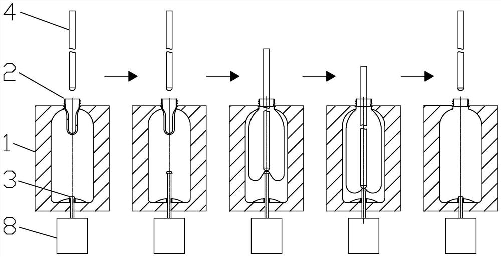
[0025] refer to figure 1 , what this embodiment discloses is a method for positioning stretch hollow blow molding in both axial and bidirectional directions. The supporting device includes a supporting rod 3 arranged at the center of the bottom of the mold cavity 1 and a driving mechanism I8 that drives the supporting rod 3 to perform telescopic movement. The top of the supporting rod 3 is a platform that will not pierce the bottom of the preform , the driving mechanism I8 is a pneumatic cylinder or a hydraulic cylinder.

[0026] Its blow molding container molding includes the following steps:

[0027] Step 1: Heat the preform 2 to the stretching temperature, and then put it into the blow molding cavity 1 for axial stretching with the help of the stretch rod 4, and at the same time inject low air pressure at the mouth of the preform 2, and pre-blow molding while stretching , this step is basically the same as the traditional stretch blow molding method;

[0028] Step 2, whe...

Embodiment 2

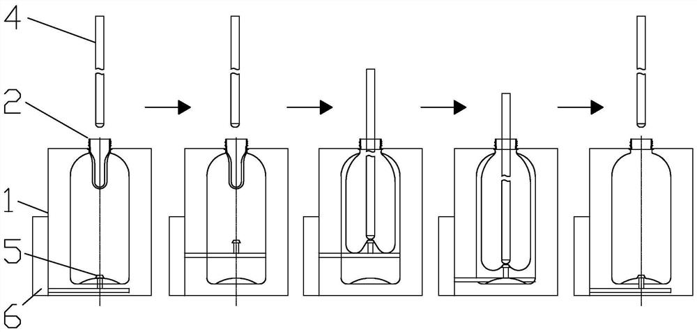
[0032] refer to figure 2 , the method adopted in this embodiment is basically the same as that in Embodiment 1, and the only difference lies in the supporting device. The supporting device includes a push rod 5 arranged in the middle of the mold cavity 1 and a drive mechanism II6 that drives the push rod 5 to move up and down. Both sides of the push rod 5 are installed on the inner side wall of the mold cavity 1, and the drive mechanism II6 is a pneumatic cylinder, a hydraulic cylinder or a motor and drives the ejector rod 5 to move up and down. The molding steps of the blow-molded container in this embodiment are basically the same as those in Embodiment 1.

Embodiment 3

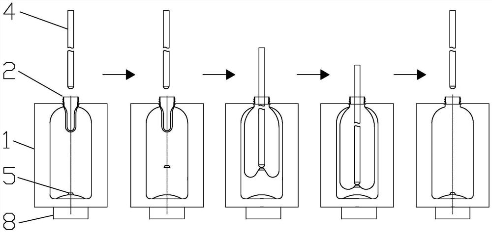
[0034] refer to image 3 , the principle of the method adopted in this embodiment is the same as that of the second embodiment, except that the way of the driving mechanism II6 is different. In this embodiment, the driving mechanism II6 is an electromagnet with variable magnetic poles. N pole, the lower end is the magnetic material of S pole, and this magnetic material is top-light and foot-heavy to avoid turning over when rising, and the purpose of controlling the movement of the push rod 5 up and down can be achieved by changing the magnetic pole of the electromagnet.

[0035] In the second step of forming the blow molding container, when stretching to the position of the supporting device, the ejector rod 5 has been suspended in the middle under the action of the electromagnet, and supports the center of the bottom of the preform that has been gradually stretched and expanded. At this time, the stretching rod 4 slows down the stretching speed or suspends stretching, and the...


PUM


Abstract

The invention provides a hollow blow molding method for positioning stretching in both axial and bidirectional directions. A supporting device for briefly supporting the bottom of the bottle blank is provided in the mold cavity. The molding of the blow molding container includes the following steps: step 1, heating the bottle blank To the stretching temperature, pre-blowing while stretching; step 2, when stretching to the position of the supporting device, the supporting device supports the center of the bottom of the preform that has been gradually stretched and expanded, and the bottom of the preform is Slow down the stretching speed or suspend stretching at the position of the supporting point, and the periphery of the supported point will continue to stretch under the action of air pressure and the inertia of its own material; step 3, after the cone bottom is formed in advance, the supporting device retracts or follows the stretching The rod moves, the stretch rod continues to stretch and injects air pressure, then cools to form the blown container. Through the support in step 2, the material at the bottom of the preform is fully stretched and distributed more evenly at the bottom of the bottle, which can achieve better cooling and shaping.

Description

technical field [0001] The invention relates to the technical field of blow molding container molding, in particular to a hollow blow molding method for axial and bidirectional orientation stretching. Background technique [0002] At present, in the process of blow molding container molding, especially in the two-step blow molding method of injection stretch blowing, the axial stretching of the preform basically touches the inner bottom of the preform through a stretch rod (round steel rod) Stretch the preform to the bottom of the cavity in one go. During the stretching process of the stretch rod, compressed air is injected at the same time, and the preform is inflated with the help of compressed air to make it cling to the cavity wall of the mold, and the hollow plastic product is obtained after cooling and shaping. When the preform is stretched to contact with the metal at the bottom of the mold cavity, the bottom of the preform cools faster, and it is difficult for the m...

Claims


Application Information

Patent Timeline
Patent Type & Authority Patents(China)
IPC IPC(8): B29C49/08
CPCB29C49/08
Inventor 谢国基姜晓平胡青春卢佳梁炎均
Owner GUANG DONG XING LIAN PRECISE MACHINERY
Why Eureka
Try Eureka