Self-pressurizing fuel tanks for space propulsion

A technology for space propulsion and fuel tanks, applied in spaceflight vehicle propulsion system devices, spaceflight equipment, spaceflight vehicles, etc., can solve problems such as unfavorable spacecraft temperature control, and achieve favorable temperature control, structure and work Simple principle, constant thrust effect

Active Publication Date: 2020-06-16
HEBEI UNIV OF TECH
View PDF6 Cites 0 Cited by
  • Summary
  • Abstract
  • Description
  • Claims
  • Application Information

AI Technical Summary

Problems solved by technology

In addition, in the adiabatic environment of outer space, the spacecraft needs to control the temperature to ensure the normal operation of the instruments it carries, and heating gas or gas is not conducive to the overall temperature control of the spacecraft.

Method used


Image

  • Self-pressurizing fuel tanks for space propulsion
  • Self-pressurizing fuel tanks for space propulsion
  • Self-pressurizing fuel tanks for space propulsion

Examples


Embodiment 1

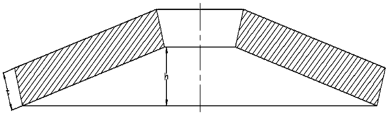
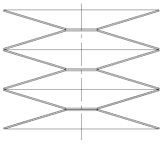
[0040] This embodiment is used for a self-pressurized fuel tank for space propulsion, such as Image 6 As shown, it includes: housing 1, piston 2, upper cover 3, screw nut mechanism 4, motor-bevel gear group 5, disc spring group 6, pipe 7, one end of the housing is connected to the pipe, and the other end is connected to the screw nut mechanism The upper cover 3, the disc spring group 6, and the piston 2 are arranged in the shell from top to bottom. The shell located in the lower space of the piston is filled with liquid fuel. A disc spring group is arranged between the piston and the upper cover. The upper end of the spring group 6 is close to the lower end surface of the upper cover, and the lower end of the disc spring group 6 is close to the bottom surface of the inner wall of the piston 2; a screw nut mechanism is connected between the upper cover and the housing, and the screw nut mechanism is connected to the motor at the same time- The bevel gear set, the motor-bevel gea...

Embodiment 2

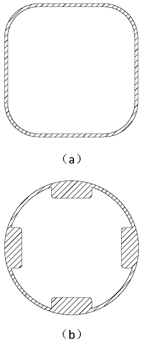
[0045] The motor-bevel gear set of the fuel tank of this embodiment is installed in the upper cover, and the installation method is exactly the same as that in the first embodiment; the installation method and function of the screw nut are also the same as the first embodiment. The difference from Example 1 is the piston and upper cover (see Picture 9 ). The piston of this embodiment (see Picture 10 ) It should be close to the non-circular inner wall of the shell, and there should be a circular guide post on the piston to install the disc spring assembly. Upper cover (see Picture 11 ) A concave round sleeve is sleeved on the circular guide post of the piston, and the upper edge of the upper cover should also be close to the non-circular inner wall of the shell. The outer diameter of the concave round sleeve is larger than the radius of the disc spring.

Embodiment 3

[0047] The fuel tank of this embodiment (see Picture 12 The motor-bevel gear set of) is installed in the upper cover, and the installation method is exactly the same as that in Embodiment 2. The installation method and function of the screw nut are also the same as in Embodiment 2. Piston (see Figure 13 ) It should be close to the non-circular inner wall of the shell, the piston is concave, and there should be a circular guide post on the piston, and a disc spring group should be installed on the circular guide post. Upper cover (see Figure 14 ) There is a concave round sleeve sleeved on the circular guide post of the piston. The difference from Embodiment 2 is that the upper edge of the upper cover must be close to the concave inner wall of the piston. The outer diameter of the concave round sleeve is larger than the radius of the disc spring.


PUM


Abstract

The present invention is used for a self-pressurized fuel tank for space propulsion. The fuel tank includes: a casing, a piston, an upper cover, a screw nut mechanism, a motor-bevel gear set, a disc spring set and a pipeline. One end of the casing is externally connected to the pipeline, and the other One end is connected to the screw nut mechanism, and the upper cover, disc spring group, and piston are arranged in sequence from top to bottom inside the housing. The housing located in the space below the piston is filled with liquid fuel, and a disc spring is arranged between the piston and the upper cover. group, the upper end of the disc spring group is close to the lower end surface of the upper cover, and the lower end of the disc spring group is close to the bottom surface of the inner wall of the piston; a screw nut mechanism is connected between the upper cover and the casing, and the screw nut mechanism is connected to the motor at the same time. The bevel gear set, the motor-bevel gear set drives the screw nut mechanism to rotate; the outer surface of the piston is in contact with the inner surface of the casing. The fuel tank utilizes the elastic force of the disc spring as power to extrude the fuel, has a simple structure, and is beneficial to the attitude control of the spacecraft.

Description

Technical field [0001] The invention belongs to the aerospace field, and is specifically a self-pressurized fuel tank for space propulsion, and is mainly used for a spacecraft orbit attitude control power system. Background technique [0002] The orbital attitude control power system is one of the important components of the spacecraft. It is mainly used for the attitude control and stabilization of various spacecraft, orbital change and orbit correction, space rendezvous and docking, and can also brake and decelerate the reentry into the atmosphere. Provide control. Gas generators are the most important part of the orbital attitude control power system. They generate thrust by blowing gas to adjust the attitude of the spacecraft. The outer space environment is zero gravity and zero pressure, so for the orbital attitude control power system using liquid fuel, the spacecraft needs to use its own power to deliver the fuel to the gas generator. Early orbital attitude control power...

Claims


Application Information

Patent Timeline
Patent Type & Authority Patents(China)
IPC IPC(8): B64G1/22B64G1/40
CPCB64G1/22B64G1/402B64G1/245
Inventor 刘远鹏
Owner HEBEI UNIV OF TECH
Why Eureka
Try Eureka