Electric tool box provided with buffer structureS
A cushioning structure and toolbox technology, which is applied in the direction of manufacturing tools, tool storage devices, and covers with auxiliary devices, etc., can solve the problems of disorderly placement of tools, inconvenient use by staff, damage to toolbox tools, etc., and achieve convenience construction, weaken the vibration amplitude, and ensure the tidy effect
- Summary
- Abstract
- Description
- Claims
- Application Information
AI Technical Summary
Problems solved by technology
Method used
Image

Examples
Embodiment 1
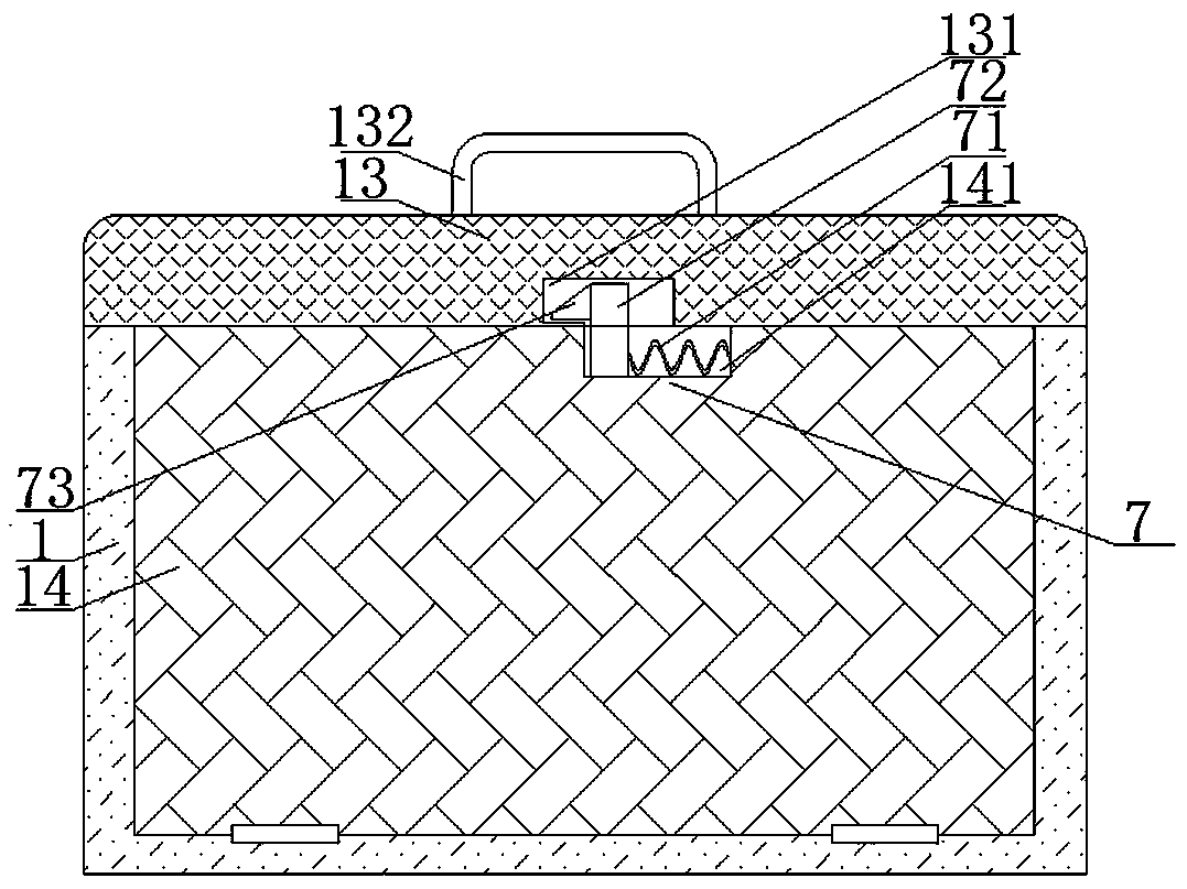
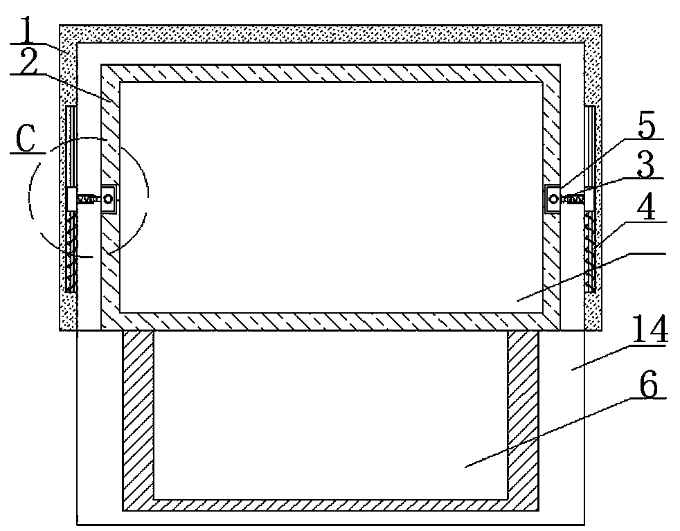
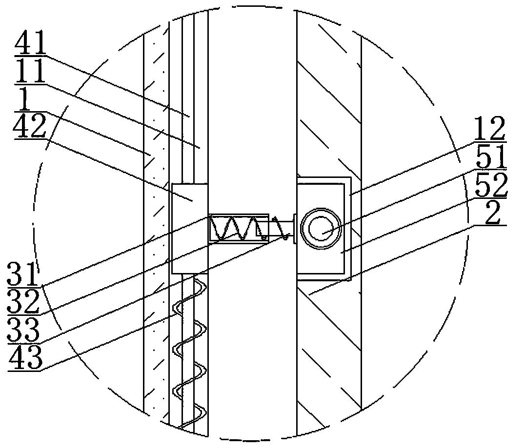
[0026] Such as Figure 1 to 5 As shown, a toolbox with a buffer function includes a box body 1, and also includes a drawer 2, an X-axis direction buffer structure 3, a Y-axis direction buffer structure 4, and a Z-axis direction buffer structure 5; in the box body 1 The inner walls of the two opposite sides are provided with Y-axis direction buffer structures 4, the side walls of the opposite sides of the tray 2 are provided with Z-axis direction buffer structures 5, and one end of the X-axis direction buffer structure 3 is buffered in the Y-axis direction. The structure 4 is connected, and the other end is connected with the Z-axis direction buffer structure 5; through the X-axis direction buffer structure 3, the Y-axis direction buffer structure 4, and the Z-axis direction buffer structure 5, the tray 2 is suspended in the box body 1. In the present invention, the drawer 2 is suspended in the box 1, and both sides of the drawer 2 are provided with an X-axis direction buffer st...
Embodiment 2
[0034] Such as Figure 4 As shown, this embodiment has the same structure as other parts of the embodiment. The difference is that the top of the drawer 2 is provided with a first placement slot 21, and the lower part of the drawer 2 is provided with an installation slot 22 for installing the drawer. The opening direction of 22 is located on the side where the second movable cover 14 is located; a drawer-type second placement groove 6 is installed in the installation groove 22, and raised third sliding blocks 61 are provided on both sides of the second placement groove 6 A third sliding groove 221 corresponding to the third sliding block 61 is provided on both sides of the mounting groove 22, and the third sliding block 61 is located in the third sliding groove 221 and slidably connected to the third sliding groove 221. The second placement slot 6 is of a drawer type. When it needs to be used, the second placement slot 6 is drawn out from the bottom of the drawer 2; two placemen...
Embodiment 3
[0036] Such as Figure 5 As shown, the structure of this embodiment is the same as that of the other parts of the second embodiment. The difference is that a limiting groove 222 is provided on the top of the mounting groove 22, a fourth spring 223 is fixed in the limiting groove 222, and the other end of the fourth spring 223 is connected There are inserting rods 224; a plurality of first slots are provided on the top of the side walls of both sides of the second placement groove 6, and the plurality of first slots are equidistantly arranged along the depth direction of the mounting groove 22, and the other inserting rods 224 Insert one end into the first slot. First slots are provided on the side walls on both sides of the first placement groove 21, and a plurality of first slots are equidistantly arranged along the length direction of the side walls of the first placement groove 21, and the insertion rod 224 is inserted in In the first slot, the length of the first placement ...
PUM
 Abstract
Description
Claims
Application Information
 - R&D Engineer
- R&D Manager
- IP Professional
- Industry Leading Data Capabilities
- Powerful AI technology
- Patent DNA Extraction
Browse by: Latest US Patents, China's latest patents, Technical Efficacy Thesaurus, Application Domain, Technology Topic.
© 2024 PatSnap. All rights reserved.Legal|Privacy policy|Modern Slavery Act Transparency Statement|Sitemap