
Cosine fringe field projection module

A cosine and fringe technology, applied in the field of 3D measurement, can solve the problems of troublesome implementation, complicated control, and high production cost, and achieve the effect of simple structure and control, simple structure control, and reduced production cost

Active Publication Date: 2019-03-12
UNIV OF ELECTRONICS SCI & TECH OF CHINA
View PDF9 Cites 8 Cited by
  • Summary
  • Abstract
  • Description
  • Claims
  • Application Information

AI Technical Summary

Problems solved by technology

The devices used in programmable projection technology are expensive and relatively complex to control, and because the stripes are actually realized by the different brightness of multiple pixels, and the pixels have a certain size limit, so they are projected The period of the fringe pattern on the display cannot be too small, but it is not suitable for the situation where a small area needs to be detected
In practical applications, in many cases, the application scenarios are relatively fixed and do not require complex projections. The advantages of programmable projections are not obvious. In contrast, the use of negatives can make the process more refined, so the size can be smaller , but the cost is lower; however, the production of the standard transmission cosine grating film is difficult, mainly because the transmittance is difficult to guarantee. At present, the main production method is photolithography, and the production cost is high. At the same time, the phase shift The realization of is cumbersome and requires fine mechanical movement to achieve

Method used


Image

  • Cosine fringe field projection module
  • Cosine fringe field projection module
  • Cosine fringe field projection module

Examples


Embodiment 1

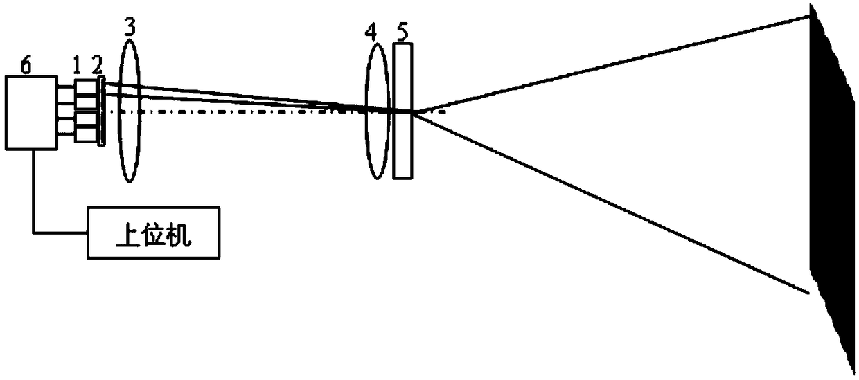
[0022] This embodiment provides a cosine fringe field projection module, its structure is as follows figure 1 As shown, it includes: a backlight source 1, a film 2, a field lens 3, a projection imaging lens 4, an expansion lens 5 and a channel control circuit 6; wherein, there are 4 binarized cosine patterns on the binarized cosine film, such as figure 2 As shown, each cosine pattern corresponds to a backlight, and optical isolation is made between each cosine pattern, so that when each backlight is turned on, only the corresponding cosine pattern can be irradiated; the four cosine patterns are shifted by 90° in sequence, correspondingly The four cosine fringe fields in the target area generated by the projection also meet the requirements of the four-step phase shift method; using the four-step time-sharing operation scheme, the external host computer selects the backlight to be turned on through the channel selection circuit, and the camera correspondingly shoots the cosine ...

Embodiment 2

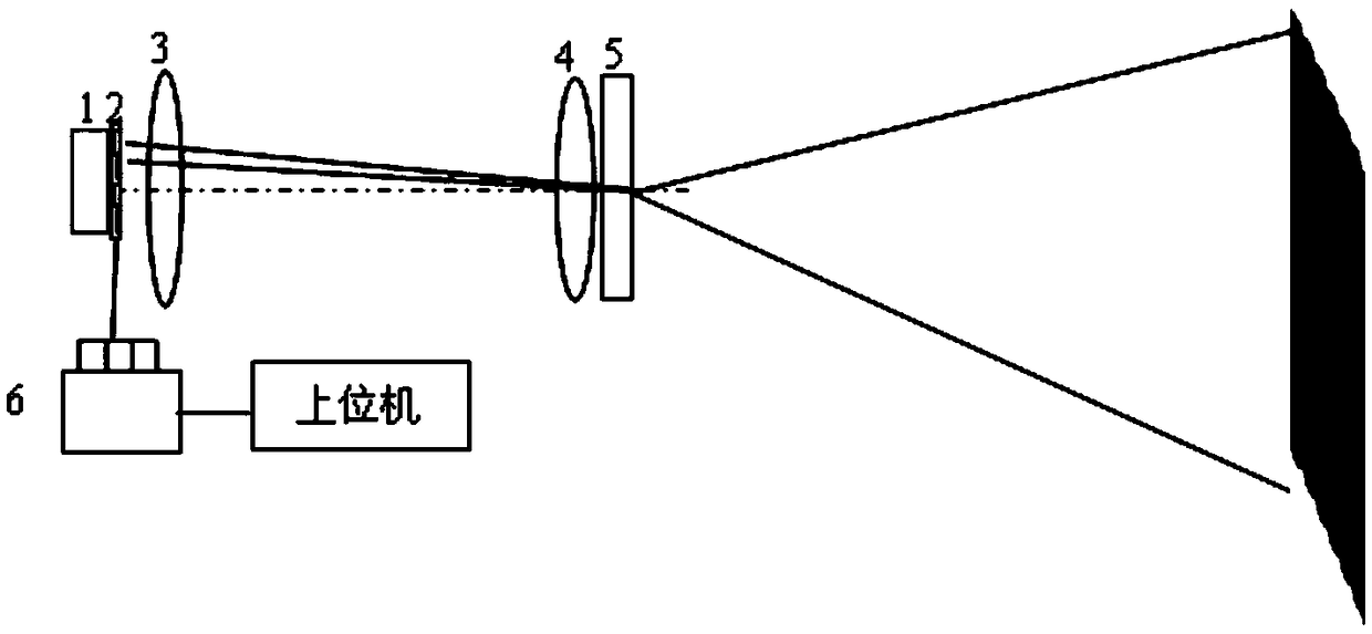
[0026] This embodiment provides a cosine fringe field projection module, its structure is as follows image 3 As shown, it comprises: backlight source 1, negative film (liquid crystal sheet) 2, field lens 3, projection imaging lens 4, expansion lens 5 and channel control circuit 6; its difference with embodiment 1 is: adopt liquid crystal sheet in the present embodiment As a negative, only one backlight source is needed; its working principle is the same as that of Embodiment 1.

[0027] The liquid crystal panel is a custom-made liquid crystal panel, and 4 binarized cosine patterns are obtained by making patterns of ITO electrodes. The liquid crystal panel has a common electrode and four control electrodes, and each control electrode corresponds to a cosine pattern, which is normally opaque. Pass through, after power on; there is only one backlight, which is shared by four cosine patterns. The binarized cosine pattern on the liquid crystal, such as Figure 4 As shown, consid...


PUM


Abstract

The invention relates to the technical field of 3D measurement, and provides a cosine fringe field projection module. The cosine fringe field projection module is particularly suitable for being usedin miniaturized 3D measuring equipment. According to the cosine fringe field projection module, binarized cosine patterns are adopted, the problem of inaccurate transmittance in the process of manufacturing a transmission-type cosine optical grating is solved, and meanwhile the manufacturing cost is greatly reduced; the four binarized cosine patterns satisfying a 90-degree phase shift relationshipare designed on a same negative film, and then through a projection imaging camera lens and an expansion camera lens, in cooperation with a channel selection circuit, four cosine fringe fields satisfying four-step phase shift are obtained. The cosine fringe field projection module is simple in structure and control, small in size and particularly suitable for 3D measuring equipment requiring whole-machine size miniaturization; meanwhile, based on the simple structure and control and low-cost components, the cost of the projection module is far lower than that of a programmable projection method.

Description

technical field [0001] The present invention relates to the technical field of 3D measurement, and mainly relates to a 3D measurement technology using cosine fringe structured light, specifically a cosine fringe field projection module. Background technique [0002] Structured light 3D measurement equipment projects structured light onto the target to be measured, shoots the target with a camera, and realizes 3D measurement by processing the captured pictures; there are many types of projected structured light, among which the cosine fringe light field is the most commonly used structured light one. For the case of projecting a cosine fringe light field, the four-step phase shift method is one of the commonly used methods. Four cosine fringe fields with the same frequency but with a phase increment of 90° are used to irradiate the target, and four photos are obtained. After processing, the height values ​​of each point are obtained. Corresponding to 3D measurement results. ...

Claims


Application Information

Patent Timeline
Patent Type & Authority Applications(China)
IPC IPC(8): G01B11/25
CPCG01B11/25
Inventor 彭仁军岳慧敏许力田明睿
Owner UNIV OF ELECTRONICS SCI & TECH OF CHINA
Learn More