
Galvanometer correction system and method

A galvanometer scanning and mirror field technology, applied in optics, instruments, opto-mechanical equipment, etc., can solve problems such as poor correction effect, achieve the effect of strong practicability, ensure accuracy, and eliminate errors

Active Publication Date: 2019-03-15
SHANGHAI MICRO ELECTRONICS EQUIP (GRP) CO LTD
View PDF6 Cites 9 Cited by
  • Summary
  • Abstract
  • Description
  • Claims
  • Application Information

AI Technical Summary

Problems solved by technology

[0004] The purpose of the present invention is to provide a vibrating mirror correction system and method, aiming to solve the problem of poor correction effect

Method used


Image

  • Galvanometer correction system and method
  • Galvanometer correction system and method
  • Galvanometer correction system and method

Examples


Embodiment Construction

[0049] A vibrating mirror correction system and method proposed by the present invention will be further described in detail below in conjunction with the accompanying drawings and specific embodiments. Advantages and features of the present invention will be apparent from the following description and claims. It should be noted that all the drawings are in a very simplified form and use imprecise scales, and are only used to facilitate and clearly assist the purpose of illustrating the embodiments of the present invention.

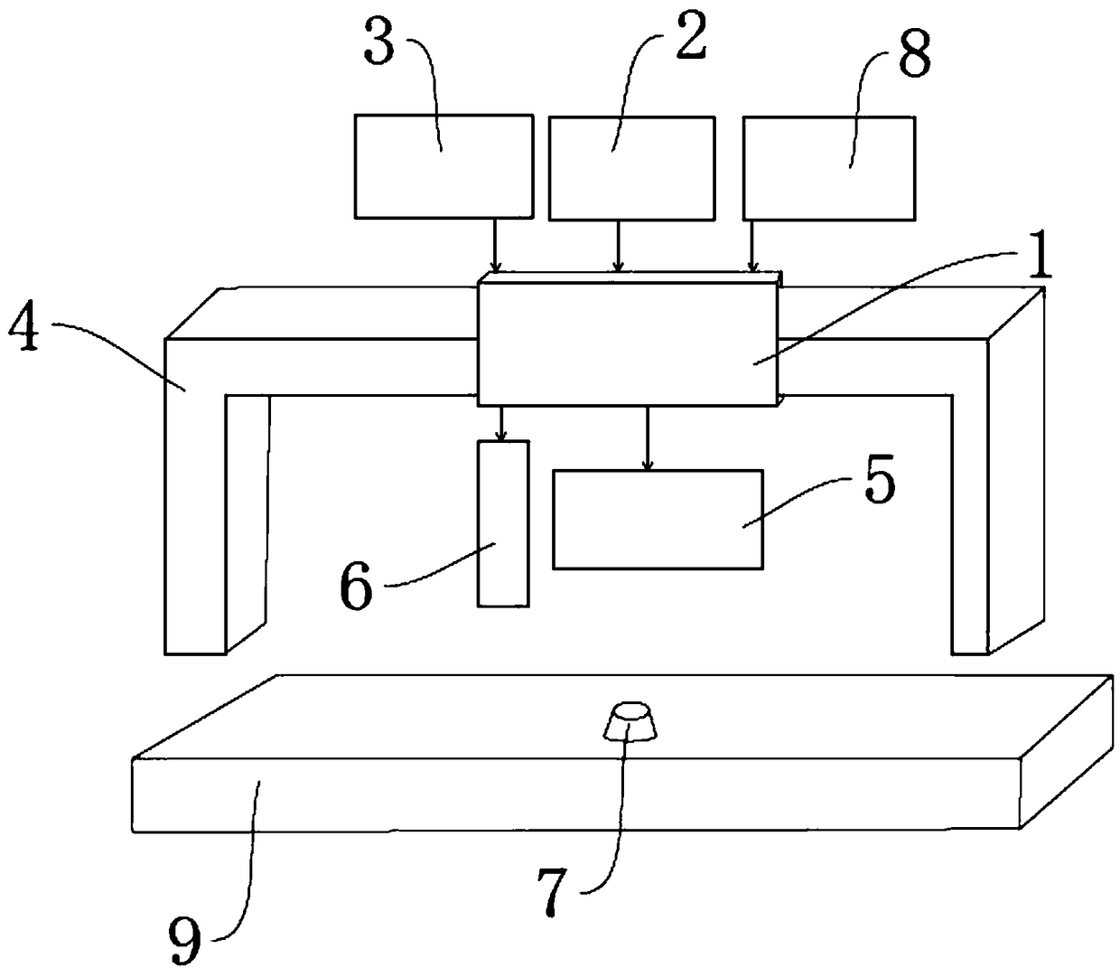
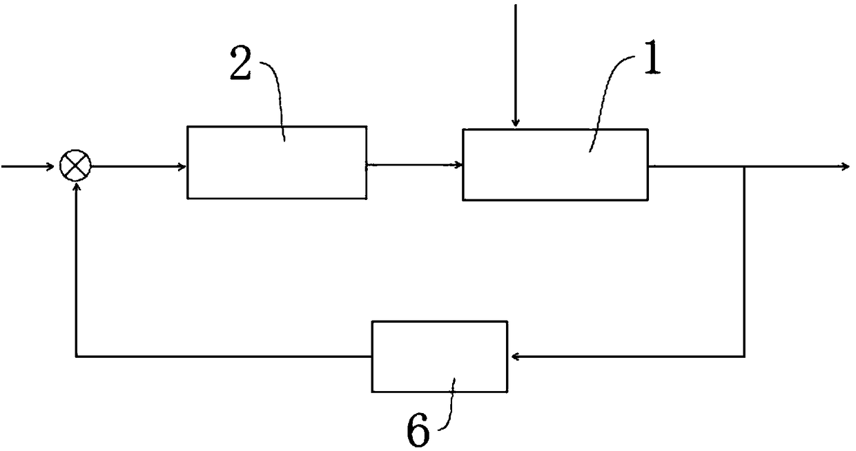
[0050] A vibrating mirror correction system and method, such as Figure 1 to Figure 3 As shown, it includes a vibrating mirror scanning system 1, a vibrating mirror controller 2, a laser device 3, a gantry frame 4, an F-theta mirror 5, a detection sampling system 6, and a spot position measuring device 7, and the F-theta mirror 5 is used for The beam of the galvanometer scanning system 1 is focused, the detection sampling system 6 is used to align the sp...


PUM


Abstract

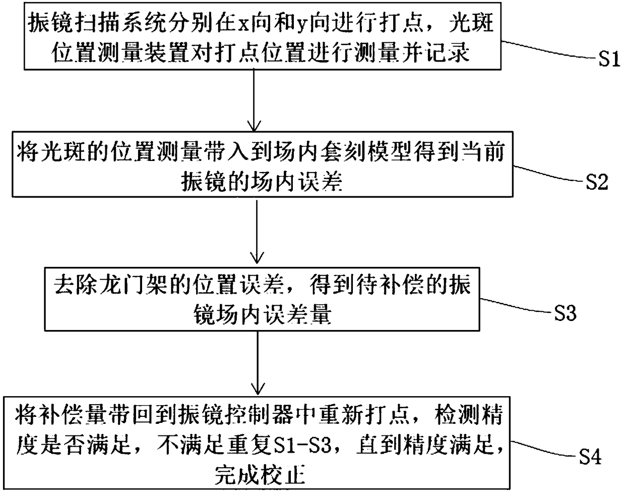
The invention provides a galvanometer correction system and method. The galvanometer correction system is implemented according to the following steps of S1, maintaining a galvanometer scanning systemfixed, allowing a galvanometer optical axis to sequentially perform in-field exposure along an x direction and a y direction, sequentially dotting in the x direction and the y direction, forming light spots, and measuring and recording positions of all light spots generated by the galvanometer scanning system by a light spot position measurement device; S2, bringing data obtained by measurement of the light spot position measurement device into an in-field alignment model to obtain an in-field error parameter of a current galvanometer; S3, performing calculation to obtain to-be-compensated galvanometer in-field error quantity; and S4, bringing the error quantity of the x direction and the y direction, obtained in the step S3, back to a galvanometer controller for dotting again, performingdetection and accuracy judgment on the light spots dotted again, repeating the steps S1 until S3 if the accuracy is not met, stopping if the accuracy is met, and completing correction. The galvanometer correction system and method, provided by the invention, are good in correction effect.

Description

technical field [0001] The invention belongs to the field of scanning devices, and relates to a vibrating mirror correction system and method. Background technique [0002] The vibrating mirror needs to be corrected before use and after installation, and then a certain amount of compensation data can be obtained, so that it can scan more accurately during use. [0003] In the existing correction method, manual correction is used, so errors in the manual correction process are prone to occur, and the correction effect is relatively poor. Contents of the invention [0004] The object of the present invention is to provide a vibrating mirror correction system and method, aiming at solving the problem of poor correction effect. [0005] In order to solve the above technical problems, the present invention provides a vibrating mirror correction method, which is realized through the following steps: [0006] S1: Keep the galvanometer scanning system still, make the optical axi...

Claims


Application Information

Patent Timeline
Patent Type & Authority Applications(China)
IPC IPC(8): G03F7/20
CPCG03F7/70358G03F7/70491G03F7/709G03F7/20
Inventor 唐江锋刘志宇朱振朋
Owner SHANGHAI MICRO ELECTRONICS EQUIP (GRP) CO LTD
Learn More