Manufacturing method of optical member
A technology for optical components and manufacturing methods, applied in chemical instruments and methods, lamination auxiliary operations, lamination, etc., can solve problems such as low antifouling properties and difficulty in erasing fingerprints
- Summary
- Abstract
- Description
- Claims
- Application Information
AI Technical Summary
Problems solved by technology
Method used
Image
Examples
Embodiment approach 1
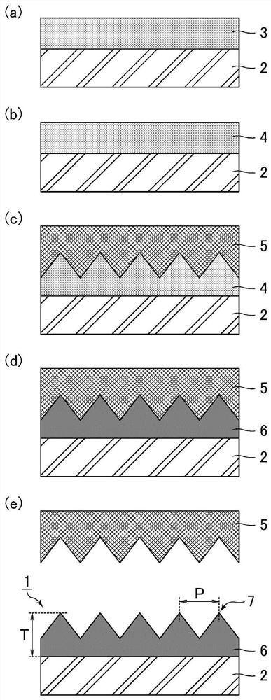
[0032] The manufacturing method of the optical member of Embodiment 1 relates to the manufacturing method of the 1st optical member of this invention. Refer to the following figure 1 The manufacturing method of the optical member of Embodiment 1 is demonstrated. figure 1 It is a cross-sectional schematic diagram for demonstrating the manufacturing method of the optical member of Embodiment 1.
[0033] (Process (1): Preparation of resin solution)
[0034] A photocurable resin and a release agent are dissolved in a solvent to prepare a resin solution 3 .
[0035] The preparation of the resin solution 3 is performed in the following procedure, for example.
[0036] (i) Various monomers, photopolymerization initiators, etc. are mixed appropriately to prepare a photocurable resin (transparent state).
[0037] (ii) A mixture of a photocurable resin and a release agent is prepared (cloudy state).
[0038] (iii) A mixture of a photocurable resin and a release agent is dissolved...
Embodiment approach 2
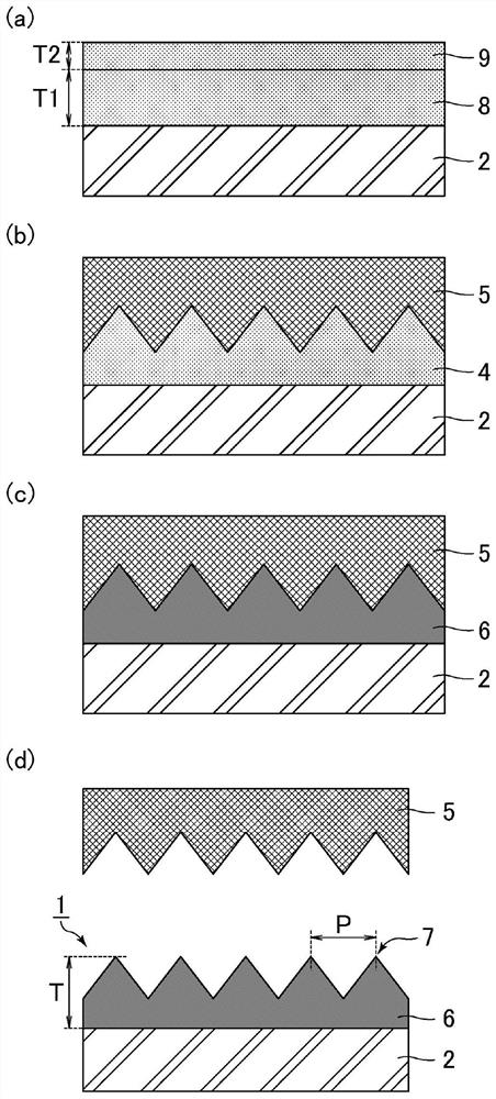
[0101] The manufacturing method of the optical member of Embodiment 2 relates to the manufacturing method of the 2nd optical member of this invention. Refer below figure 2 The manufacturing method of the optical member of Embodiment 2 is demonstrated. figure 2 It is a cross-sectional schematic diagram for demonstrating the manufacturing method of the optical member of Embodiment 2. The manufacturing method of the optical member of Embodiment 2 is the same as the manufacturing method of the optical member of Embodiment 1, except that the photocurable resin and the release agent are divided into two layers and applied, and then the two layers are integrated. , so descriptions are appropriately omitted for the repetitions.
[0102] (Process (1): Application of the first resin and the second resin)
[0103] Such as figure 2 As shown in (a), the first resin 8 containing a photocurable resin is applied to the surface of the substrate 2 . Next, the second resin 9 containing a...
Embodiment approach 3
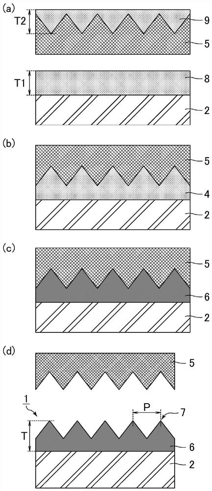
[0124] The manufacturing method of the optical member of Embodiment 3 relates to the manufacturing method of the 2nd optical member of this invention. Refer below image 3 The manufacturing method of the optical member of Embodiment 3 is demonstrated. image 3 It is a cross-sectional schematic diagram for demonstrating the manufacturing method of the optical member of Embodiment 3. The manufacturing method of the optical member in Embodiment 3 is the same as the manufacturing method of the optical member in Embodiment 2 except that the second resin is applied to the surface of the mold. Therefore, descriptions of overlapping parts are appropriately omitted.
[0125] (Process (1): Application of the first resin and the second resin)
[0126] Such as image 3 As shown in (a), the first resin 8 containing a photocurable resin is applied to the surface of the substrate 2 . Next, the second resin 9 containing a release agent is applied to the surface (concave-convex surface) of...
PUM
| Property | Measurement | Unit |
|---|---|---|
| thickness | aaaaa | aaaaa |
| height | aaaaa | aaaaa |
| thickness | aaaaa | aaaaa |
Abstract
Description
Claims
Application Information
 - R&D
- Intellectual Property
- Life Sciences
- Materials
- Tech Scout
- Unparalleled Data Quality
- Higher Quality Content
- 60% Fewer Hallucinations
Browse by: Latest US Patents, China's latest patents, Technical Efficacy Thesaurus, Application Domain, Technology Topic, Popular Technical Reports.
© 2025 PatSnap. All rights reserved.Legal|Privacy policy|Modern Slavery Act Transparency Statement|Sitemap|About US| Contact US: help@patsnap.com


