
Step tool

A tool and step technology, applied in step drills, drill accessories, manufacturing tools, etc., can solve the problems of increased processing costs, single tool functions, and high equipment prices, improve processing efficiency, solve insufficient tool positions, and reduce processing costs. Effect

Pending Publication Date: 2019-03-19
GAOAN TIANFU OPTOELECTRONICS TECH
View PDF0 Cites 0 Cited by
  • Summary
  • Abstract
  • Description
  • Claims
  • Application Information

AI Technical Summary

Problems solved by technology

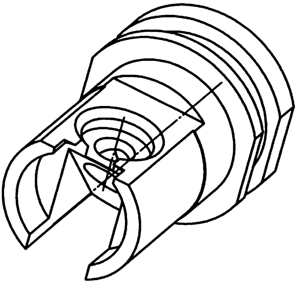
[0002] The existing equipment on the market has only three power heads, and high-end equipment can only have four power heads. According to the normal practice, five power knives are required to process. figure 2 In other words, only four processes can be processed first, and one process is left for the milling machine to process one piece, and the milling machine processes one process, the shape tolerance and appearance cannot meet the requirements of the drawing, and this product is used for optical communication. The burr requirements are very high, and this processing method cannot meet the drawing and application requirements. If you purchase high-configuration equipment, not only the equipment price is extremely high, but also the delivery period of the new equipment is long, which cannot guarantee the delivery date of the customer's order, and the processing cost will also become Multiplied, no longer have the cost advantage, the existing tools have a single function, insufficient practicability

Method used


Image

  • Step tool
  • Step tool

Examples


Embodiment Construction

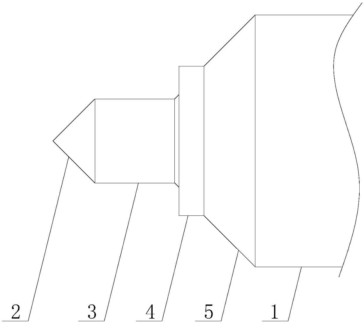
[0017] The present invention is described in further detail now in conjunction with accompanying drawing. These drawings are all simplified schematic diagrams, which only illustrate the basic structure of the present invention in a schematic manner, so they only show the configurations related to the present invention.

[0018] Such as figure 1 As shown, a stepped tool includes a handle 1 and a cutter head, the handle 1 is connected to the cutter head, the cutter head includes a center drill 2, a drill bit 3, a milling cutter 4 and a chamfering cutter 5, and the center drill 2 is conical, Both the drill bit 3 and the milling cutter 4 are cylindrical, the chamfering cutter 5 is a truncated cone, the center drill 2 matches the drill bit 3, the drill bit matches the milling cutter 4, the milling cutter 4 matches the chamfering cutter 5, and the chamfering cutter 5 matches the cutter The shank 1 is matched, the center drill 2, the drill bit 3, the milling cutter 4 and the chamfe...


PUM


Abstract

The invention relates to a step tool. The step tool comprises a tool shank and a tool bit, wherein the tool shank is connected to the tool bit; the tool bit comprises a central drill, a drill bit, a milling cutter and a chamfering knife, the central drill, the drill bit, the milling cutter and the chamfering knife are coaxially arranged, and are distributed in a stepped mode; and the central drill, the drill bit, the milling cutter, the chamfering knife and the tool shank are sequentially connected together. The step tool can effectively solve a cutter spacing deficiency phenomenon, and can process two holes and chamfer once; and meanwhile, various tool functions are combined, so that occurrence of burrs at mutually crossed parts, during processing, of tools is avoided, and therefore, processing efficiency is obviously improved, and product processing cost is reduced.

Description

technical field [0001] The invention relates to the field of drilling tools, in particular to a stepped tool. Background technique [0002] The existing equipment on the market has only three power heads, and high-end equipment can only have four power heads. According to the normal practice, five power knives are required to process. figure 2 In other words, only four processes can be processed first, and one process is left for the milling machine to process one piece, and the milling machine processes one process, the shape tolerance and appearance cannot meet the requirements of the drawing, and this product is used for optical communication. The burr requirements are very high, and this processing method cannot meet the drawing and application requirements. If you purchase high-configuration equipment, not only the equipment price is extremely high, but also the delivery period of the new equipment is long, which cannot guarantee the delivery date of the customer's orde...

Claims


Application Information

Patent Timeline
Patent Type & Authority Applications(China)
IPC IPC(8): B23B51/00B23B51/08
CPCB23B51/009B23B51/08
Inventor 邹支农
Owner GAOAN TIANFU OPTOELECTRONICS TECH
Learn More