
High-stability solar energy collecting device

A technology of solar energy collection and high stability, applied in the field of solar energy collection, can solve the problems of easy shaking of the end, low operation stability of the device, large shaking, etc., and achieve the effect of efficiently absorbing sunlight energy

Pending Publication Date: 2019-03-19
张正文
View PDF0 Cites 0 Cited by
  • Summary
  • Abstract
  • Description
  • Claims
  • Application Information

AI Technical Summary

Problems solved by technology

[0002]At present, the end of the torque tube on the solar energy collection device uses a rotary machine to drive a very long row, and the longer row can reach 180m, because the torque of the torque tube is not enough , it is easy to cause the mirror farther away from the rotary machine to lose accuracy due to the twist of the torque tube
Moreover, the end is easy to shake, especially when encountering strong winds, it is prone to tremors, large-scale shaking, etc., and the operation stability of the whole device is low.

Method used


Image

  • High-stability solar energy collecting device
  • High-stability solar energy collecting device
  • High-stability solar energy collecting device

Examples


Embodiment 1

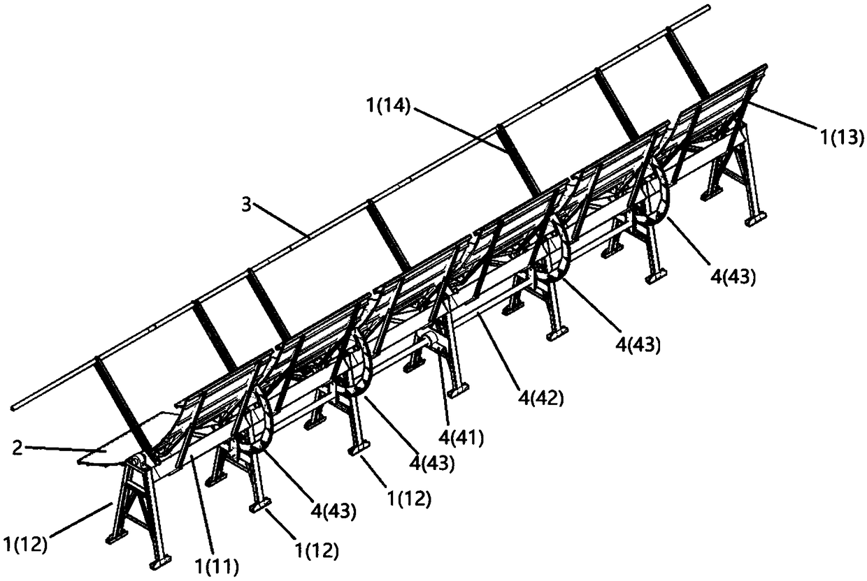
[0026] Please refer to Figure 1 to Figure 4 , the present embodiment provides a high-stability solar energy collection device, including a mounting frame assembly 1 , a plurality of reflector groups 2 arranged on the mounting frame assembly 1 , and a vacuum tube group 3 disposed above the reflector group 2 . The solar energy collection device of this embodiment also includes a rotation drive mechanism 4 connected to the installation bracket assembly 1, wherein the rotation drive mechanism 4 includes a drive assembly 41, a main transmission rod 42 extending along the length direction of the installation bracket assembly 1, connecting On the main transmission rod 42 and connected to some transmission wheel sets 43 of the mounting bracket assembly 1, the transmission wheel set 43 includes a main transmission wheel 431 connected to the main transmission rod 42, and engaged on the main transmission wheel 431 and connected to A slave transmission wheel 432 of the bracket assembly 1...

Embodiment 2

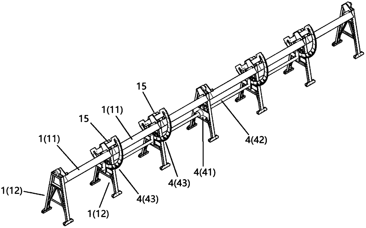
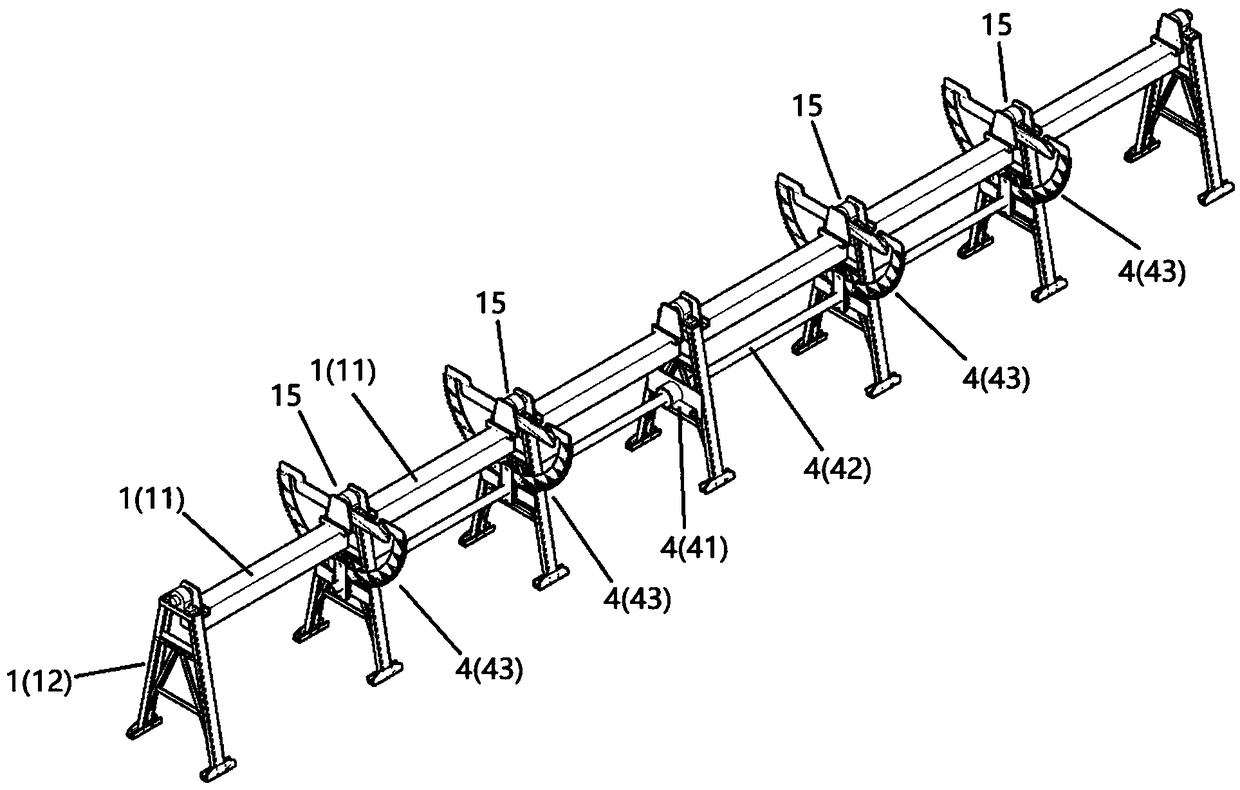
[0037] Such as Figure 6 and Figure 7 As shown, the main difference between this embodiment and Embodiment 1 is that the driving assembly 41 in this embodiment is sleeved on the periphery of the bearing rod 152 of one of the bearing assemblies 15, that is, the driving assembly 41 is installed on the bearing housing 151 at other positions. on the same axis. Meanwhile, the drive assembly 41 can also be a rotary reducer, a worm gear reducer or a gear reducer.

[0038] The specific working principle is:

[0039] When the drive assembly 41 drives the torque tube 11, it also drives the slave transmission wheel 432 of the transmission wheel set 43 to rotate synchronously; then, the main transmission wheel 431 is driven by the slave transmission wheel 432, and the main transmission wheel 431 drives the main transmission rod 42 again; The other main transmission wheels 431 arranged on the main transmission rod 42 drive the slave transmission wheels 432 at other positions, and final...


PUM


Abstract

The invention discloses a high-stability solar energy collecting device. The high-stability solar energy collecting device comprises a mounting bracket assembly, a plurality of reflector groups arranged on the mounting bracket assembly, a vacuum tube group arranged above the reflector groups, and a rotary driving mechanism connected to the mounting bracket assembly. The rotary driving mechanism comprises a driving assembly, a main transmission rod extending in the length direction of the mounting bracket assembly, a plurality of transmission wheel groups connected to the main transmission rodand connected to the mounting bracket assembly, wherein the transmission wheel groups comprise a main transmission wheel connected to the main transmission rod, and a secondary transmission wheel meshing with the main transmission wheel and connected to the mounting bracket assembly. According to the high-stability solar energy collecting device, the reflector groups on the whole device can obtainthe same and stable high-precision rotation angle, the tail ends of the reflector groups do not shake, and the whole device can stably operate even in strong wind, so that the reflector groups can rotate to an angle suitable for sunlight rays, and solar energy can be absorbed more efficiently.

Description

technical field [0001] The invention relates to the field of solar energy collection, in particular to a high-stability solar energy collection device. Background technique [0002] At present, the end of the torque tube on the solar energy collection device uses a rotary machine to drive a very long column, and the longest column can reach 180m. Due to the insufficient torque of the torque tube, it is easy to cause the reflector at a position farther from the rotary machine. Because the torque The tube twists and loses precision. Moreover, the end is easy to shake, especially when encountering strong winds, it is prone to tremors, large-scale shaking and other phenomena, and the operation stability of the whole device is low. Contents of the invention [0003] In view of the above deficiencies, the object of the present invention is to provide a high-stability solar energy collection device, so that the reflector groups on the entire device can obtain the same and stable...

Claims


Application Information

Patent Timeline
IPC IPC(8): F24S10/40F24S10/70F24S23/70F24S30/425
CPCY02E10/44Y02E10/47
Inventor 张正文
Owner 张正文
Features
  • Generate Ideas
  • Intellectual Property
  • Life Sciences
  • Materials
  • Tech Scout
  • Unparalleled Data Quality
  • Higher Quality Content
  • 60% Fewer Hallucinations
Learn More