Parallel rope drive antenna base mechanism

A technology of rope drive and antenna seat, which is applied in the field of parallel rope drive antenna seat mechanism, can solve problems such as the inability to ensure accurate tracking of the antenna reflection surface, insufficient processing accuracy and installation error, and application limitations of the rope drive mechanism, etc., achieving low cost and lightening The overall weight and the effect of simplifying the structure of the antenna base

Active Publication Date: 2019-03-19
YANSHAN UNIV
View PDF10 Cites 5 Cited by
  • Summary
  • Abstract
  • Description
  • Claims
  • Application Information

AI Technical Summary

Problems solved by technology

Most of the existing antennas are supported by series or parallel mechanisms. The support mechanism of the antenna base is usually connected by multiple connecting rods and the kinematic pairs between the connecting rods. The connecting rods are elastically deformed. There are often gaps, and in high-precision operating occasions, it is impossible to guarantee the accurate tracking of the specific trajectory of the antenna reflection surface
At the same time, the parallel mechanism is usually over-constrained, and its disassembly and installation are often difficult, especially when the antenna fails, it often takes a lot of time and manpower to replace the supporting mechanism
In contrast, the rope-driven mechanism can not only reduce the load of the mechanical system, improve the transmission performance of the mechanism, but also effectively reduce the vibration of the mechanism movement. However, the disadvantage of the rope-driven mechanism is that the rope can only provide tension and cannot provide support.
In certain application scenarios, the application of the rope drive mechanism is also limited

Method used


Image

  • Parallel rope drive antenna base mechanism
  • Parallel rope drive antenna base mechanism
  • Parallel rope drive antenna base mechanism

Examples


Embodiment Construction

[0018] Exemplary embodiments, features, and performance aspects of the present invention will be described in detail below with reference to the accompanying drawings. The same reference numbers in the figures indicate functionally identical or similar elements. While various aspects of the embodiments are shown in drawings, the drawings are not necessarily drawn to scale unless specifically indicated.

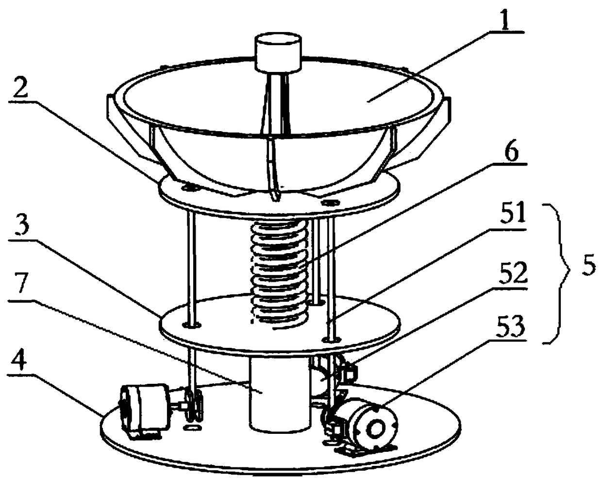
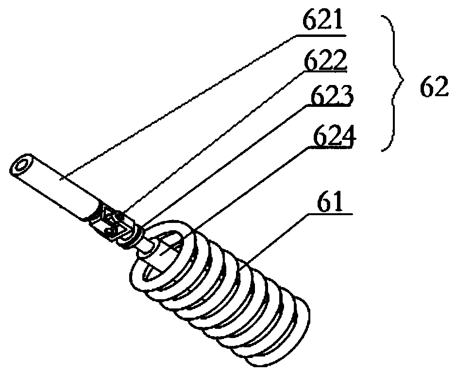
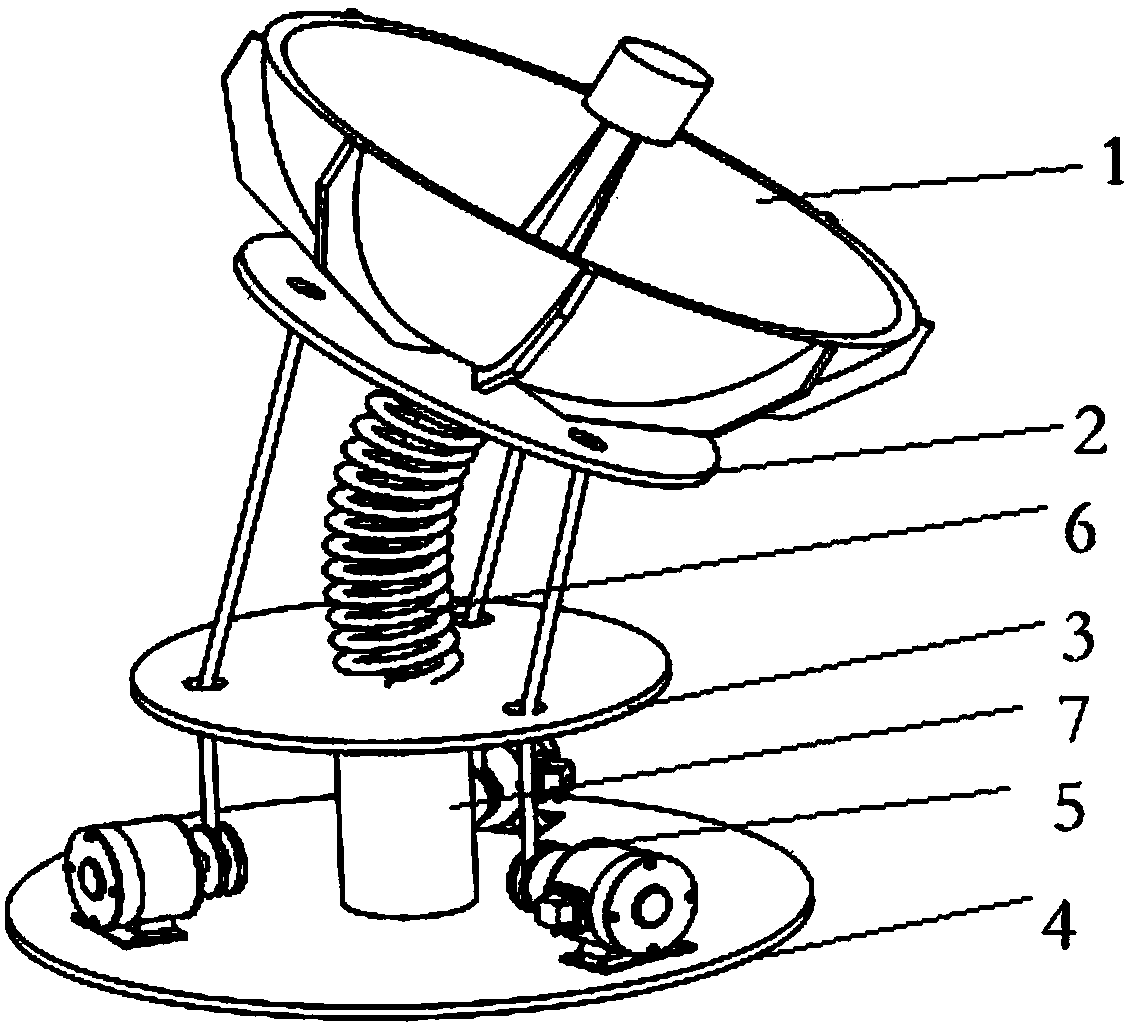
[0019] Such as figure 1 As shown, a parallel rope-driven antenna seat mechanism includes an antenna reflection surface 1, a moving platform 2, a fixed platform 3, a base platform 4, a support shaft 7, a central branch chain 6 and a rope driving device 5, and the antenna reflection surface 1 Fixed on the upper surface of the moving platform 2, the two ends of the central branch chain 6 are respectively fixed on the center position of the lower surface of the moving platform 2 and the upper surface of the fixed platform 3, and the two ends of the support shaft 7 are respectivel...


PUM


Abstract

The invention relates to a parallel rope drive antenna base mechanism which comprises an antenna reflecting surface, a moving platform, a fixed platform, a base platform, a supporting shaft, a centralbranched chain and rope drive devices. The antenna reflecting surface is fixed on the upper surface of the moving platform. Two ends of the central branched chain are fixed at the central positions of the lower surface of the moving platform and the upper surface of the fixed platform respectively. Two ends of the supporting shaft are fixed at the middle positions of the lower surface of the fixed platform and the upper surface of the base platform respectively. The axes of the central branched chain and the supporting shaft are collinear. A number of rope drive devices are circumferentiallyand evenly distributed between the moving platform and the base platform. The rope drive devices work with the central branched chain to realize continuous rotation of the antenna reflecting surface and the moving platform around the central axis. The problem of a blind cone area of a traditional pitch-orientation antenna tracking a satellite over the zenith is solved. Satellite tracking in the entire airspace can be realized. The parallel rope drive antenna base mechanism has the advantages of high pointing accuracy and good dynamic characteristics.

Description

technical field [0001] The invention belongs to the technical field of antenna devices, and in particular relates to a parallel rope-driven antenna seat mechanism. Background technique [0002] At present, with the increasing frequency of sky exploration activities in various countries in the world, the demand for high-end equipment used in satellite communication, military reconnaissance, radar monitoring and deep space exploration is particularly urgent. Radar antennas can assist researchers in sending and receiving data signals, and are important equipment for various space exploration and communication activities. The pointing and tracking accuracy of radar antennas are key indicators to measure its performance. The antenna pedestal is an important carrier used to support the antenna satellite body. Its function is to drive the antenna to track and point the target accurately and in real time according to specific work requirements and specific motion trajectories, and s...

Claims


Application Information

Patent Timeline
Patent Type & Authority Applications(China)
IPC IPC(8): H01Q1/08H01Q1/12H01Q3/20H01Q3/02H01Q19/12
Inventor 侯雨雷张国兴郑雪山随永祥张继永曾达幸
Owner YANSHAN UNIV
Why Eureka
Try Eureka