Phase change heat sink manufacturing process

A manufacturing process and radiator technology, which can be used in cooling/ventilation/heating transformation, modification with liquid cooling, electrical components, etc., which can solve the problems of large horizontal temperature difference and vertical temperature difference, poor heat dissipation effect, and inability to transfer heat evenly. To achieve the effect of reducing the difficulty of operation

Inactive Publication Date: 2019-03-19
李洪刚
View PDF6 Cites 0 Cited by
  • Summary
  • Abstract
  • Description
  • Claims
  • Application Information

AI Technical Summary

Problems solved by technology

[0004] However, when using the above heat sink combination method, the thermal resistance between the PCB board and the heat sink is very large, the heat on the PCB cannot be evenly transferred to the heat sink surface, and the lateral temperature difference and vertical temperature difference of each point on the heat sink surface are large. The overall utilization rate of the radiator is low, resulting in poor heat dissipation effect, and there is room for improvement in the prior art

Method used


Image

  • Phase change heat sink manufacturing process

Examples


Embodiment Construction

[0031] The present invention will be described in further detail below in conjunction with the accompanying drawings.

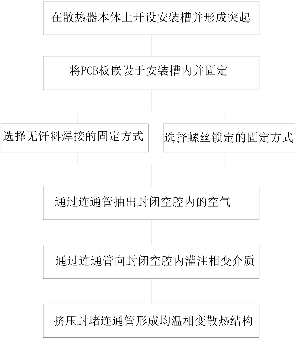
[0032] A manufacturing process of a phase change radiator. The operator first creates an installation groove on the installation surface of the radiator body, and then embeds the PCB board in the installation groove and fixes it, and the bottom surface of the PCB board and the groove bottom of the installation groove A closed cavity is formed, and then the air in the closed cavity is drawn out through the connecting pipe preformed on the radiator body, and then the phase change medium is poured into the closed cavity through the connecting pipe, and finally the connecting pipe is closed, so that the radiator The main body, the closed cavity and the phase-change medium together form a uniform-temperature phase-change heat dissipation structure.

[0033] The specific steps are described below:

[0034] The body of the S1 radiator has a square structure. The op...


PUM


Abstract

The invention discloses a phase change heat sink manufacturing process, and relates to the technical field of heat sink bonding, comprising the following steps of S1, disposing a mounting slot on themounting surface of a heat sink body; S2, embedding and fixing a PCB in the mounting slot, wherein a closed cavity is formed between the PCB and the bottom of the mounting slot; S3, exhausting the airin the closed cavity by a communication tube preformed on the heat sink body; S4, pouring a phase change medium into the closed cavity by the communication pipe; and S5, sealing the communication tube to form a uniform temperature phase change heat dissipation structure. The uniform temperature phase change heat dissipation structure is filled with the phase change medium so as to reduce the thermal resistance between the PCB and the heat sink body. Thus, the heat on the PCB is uniformly transferred to the surface of the heat sink body, and the transverse temperature difference among variouspoints on the surface of the heat sink body and the longitudinal temperature difference of the heat sink body are reduced, thereby achieving a purpose of improving the surface utilization rate of theheat sink body and a purpose of improving a heat dissipation effect.

Description

technical field [0001] The invention relates to the technical field of heat sink combination, in particular to a manufacturing process of a phase change heat sink. Background technique [0002] The electronic components on the PCB will dissipate a lot of heat during normal use and accumulate on the PCB and the electronic components, and a large amount of stored heat will affect the normal use of the electronic components, so it is necessary to check the PCB and the electronic components. The electronic components on it are heat-dissipated. [0003] Usually, the PCB board and electronic components are dissipated by adding a heat sink. The existing way of combining the heat sink is to combine the PCB board and the heat sink through screws, and add thermal paste between the two to squeeze out the air in the gap between the heat sink and the PCB board. There is a temperature difference between the radiator and the PCB board, and the heat generated by the electronic components ...

Claims


Application Information

Patent Timeline
Patent Type & Authority Applications(China)
IPC IPC(8): H05K7/20
CPCH05K7/2029H05K7/205
Inventor 李洪刚
Owner 李洪刚
Why Eureka
Try Eureka