Auxiliary magnetic field device for magneto plastic wire drawing and using method thereof

An auxiliary magnetic field and plasticity technology, applied in metal processing, metal processing equipment, manufacturing tools, etc., can solve the problems of lack of measurement accuracy, cumbersome measurement steps, inability to measure the uniform magnetic field of Helmholtz coils, etc., to reduce drawing The effect of uniform force and magnetic field

Active Publication Date: 2019-03-22
TAICANG FANSHENG ELECTRONICS TECH CO LTD
View PDF7 Cites 1 Cited by
  • Summary
  • Abstract
  • Description
  • Claims
  • Application Information

AI Technical Summary

Problems solved by technology

[0004] The Hall effect is widely used in physical quantity measurement and engineering technology, and can directly or indirectly detect the magnetic field. However, the rotating Hall effect sensor designed based on the principle of differential uniform magnetic field can only be used to measure the magnetic field lines around a single circular DC coil. distribution, it is impossible to measure the uniform magnetic field superimposed in the middle area of ​​the Helmholtz coil, and the measurement steps are cumbersome and the measurement accuracy is lacking. Therefore, it is necessary to design a simple, efficient and accurate magnetic field measurement device for measuring Uniform magnetic field in the middle region of the Helmholtz coil parallel to the wire drawing direction

Method used


Image

  • Auxiliary magnetic field device for magneto plastic wire drawing and using method thereof
  • Auxiliary magnetic field device for magneto plastic wire drawing and using method thereof
  • Auxiliary magnetic field device for magneto plastic wire drawing and using method thereof

Examples


Embodiment Construction

[0030] The following will clearly and completely describe the technical solutions in the embodiments of the present invention with reference to the accompanying drawings in the embodiments of the present invention. Obviously, the described embodiments are only some, not all, embodiments of the present invention. Based on the embodiments of the present invention, all other embodiments obtained by persons of ordinary skill in the art without making creative efforts belong to the protection scope of the present invention.

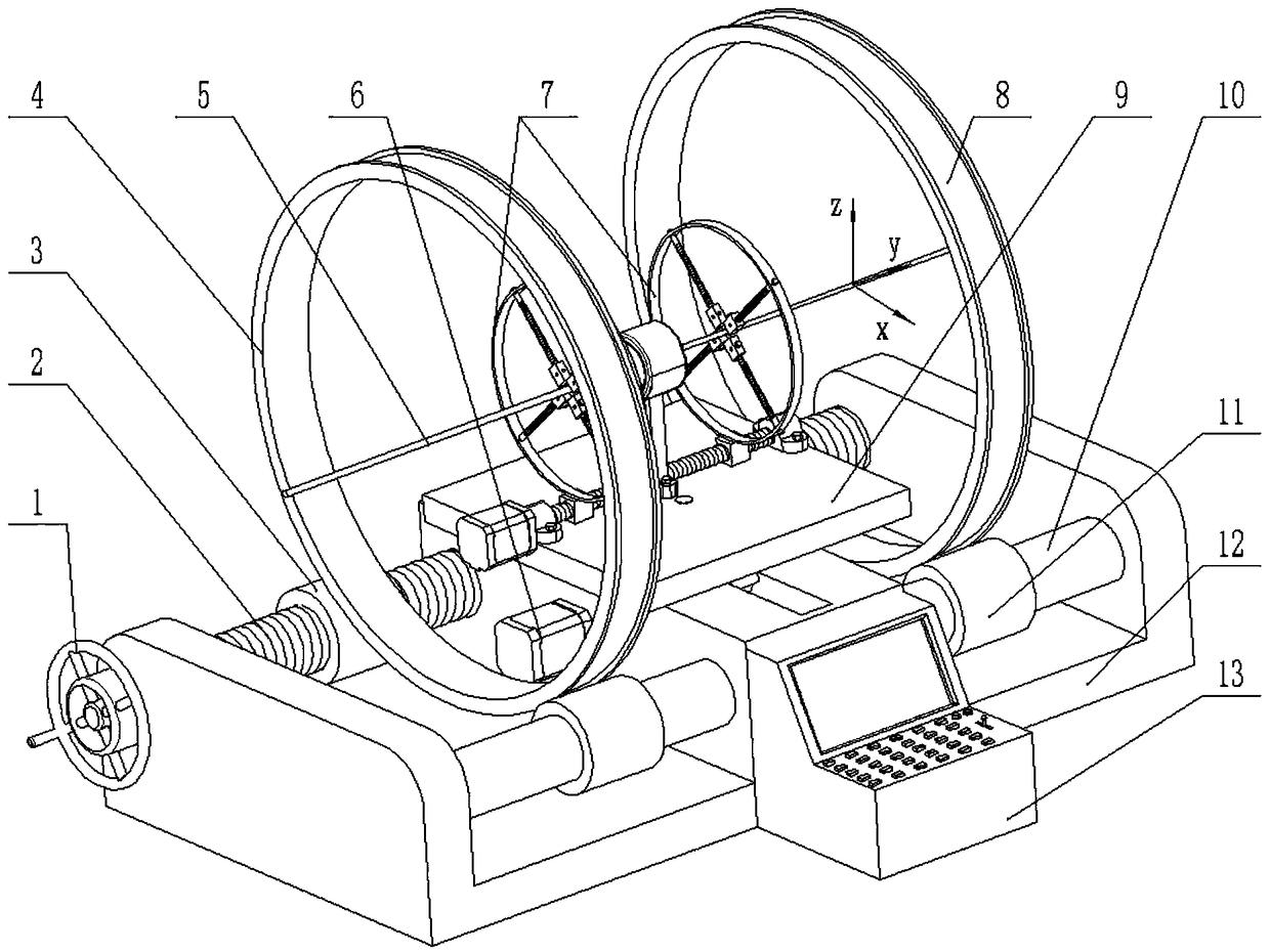
[0031] The purpose of the present invention is to provide an auxiliary magnetic field device for magnetoplastic wire drawing and its use method to solve the problems in the prior art, accurately measure the magnetic field around the wire drawing material, and provide a uniform magnetic field environment for magnetoplastic wire drawing .

[0032] In order to make the above objects, features and advantages of the present invention more comprehensible, the presen...


PUM


Abstract

The invention discloses an auxiliary magnetic field device for magneto plastic wire drawing. The auxiliary magnetic field device comprises a machine frame, wherein a protruding part is arranged in themiddle of the machine frame, a first screw rod and a sliding rod which are parallel to each other and penetrate the protruding part are arranged in the machine frame, the first screw rod can rotate,a hand wheel is fixedly arranged at one end of the first screw rod, the thread directions of the portions, on the two sides of the protruding part, of the first screw rod are opposite, and each of thetwo sides of the protruding part is provided with a magnetic field generating unit; a first motor is fixedly arranged on the protruding part, a supporting plate is arranged on the top of the first motor in a sliding mode, and the supporting plate can move; a magnetic field detection part and a wire drawing die are arranged above the supporting plate, and a power supply control and signal acquisition platform is arranged on the machine frame. The auxiliary magnetic field device for magneto plastic wire drawing and the using method of the auxiliary magnetic field device can accurately measure the magnetic field around wire drawing material, so that a uniform magnetic field can be obtained through continuous adjusting to guarantee for the magneto plastic wire drawing.

Description

technical field [0001] The invention relates to the technical field of metal processing equipment, in particular to an auxiliary magnetic field device used in magnetoplastic wire drawing and its application method. Background technique [0002] Although the theory of magnetoplasticity has existed for a long time, it has been limited to the study of some plasmonic crystals, and there are almost no reports on non-ferromagnetic metals. Magnetoplastic wire drawing technology is a new wire drawing production technology that has only appeared in recent years. Strong magnetic fields can induce plastic deformation of materials, which is manifested as the "magnetoplastic" effect. At present, in the process of material modification, a relatively stable magnetization environment is provided for material processing, which can promote the rearrangement of atoms, facilitate the formation of low-energy state dislocation structures, reduce the interfacial energy of materials, and promote th...

Claims


Application Information

Patent Timeline
IPC IPC(8): B21C1/02B21C51/00
Inventor 李大龙杨玉星
Owner TAICANG FANSHENG ELECTRONICS TECH CO LTD
Why Eureka
Try Eureka