Wire forming machine of portal frame structure

A structure wire and gantry technology, which is applied in the field of gantry structure wire forming machines, can solve the problems of affecting the ductility and toughness of the wire, affecting the production efficiency, and being unable to form at one time, so as to improve production efficiency, convenient operation and reasonable structure. Effect

Inactive Publication Date: 2019-03-22
徐州奔蓝机械科技有限公司
View PDF8 Cites 1 Cited by
  • Summary
  • Abstract
  • Description
  • Claims
  • Application Information

AI Technical Summary

Problems solved by technology

[0002] With the continuous improvement of people's living standards, the daily necessities and small furniture in the family have gradually changed from practical effects to artistic forms, especially for small objects. A shelf for placing sheet-shaped objects is mainly composed of multiple gantry frames. The steel wires of the structure are welded by stacking the main line. Its structure is simple and the storage items are highly recognizable so that it is easy to select the required items. Take out the wire from the reel material and cut it straight; then put the wire into the wire bending machine to bend both sides of the wire; put the bent wire into the punching machine to punch the arc near the bend; finally put The semi-finished wire is placed on the U-shaped mold for the gantry forming process. The whole process requires workers to adjust the position of the wire many times, and it cannot be formed at one time. A lot of man-hours are spent on the action of picking up and decorating parts, which affects production efficiency and constantly adjusts the processing. The position will be distorted, which affects the ductility and toughness of the wire, so a new technical solution needs to be proposed to solve the above problems

Method used


Image

  • Wire forming machine of portal frame structure
  • Wire forming machine of portal frame structure

Examples


Embodiment Construction

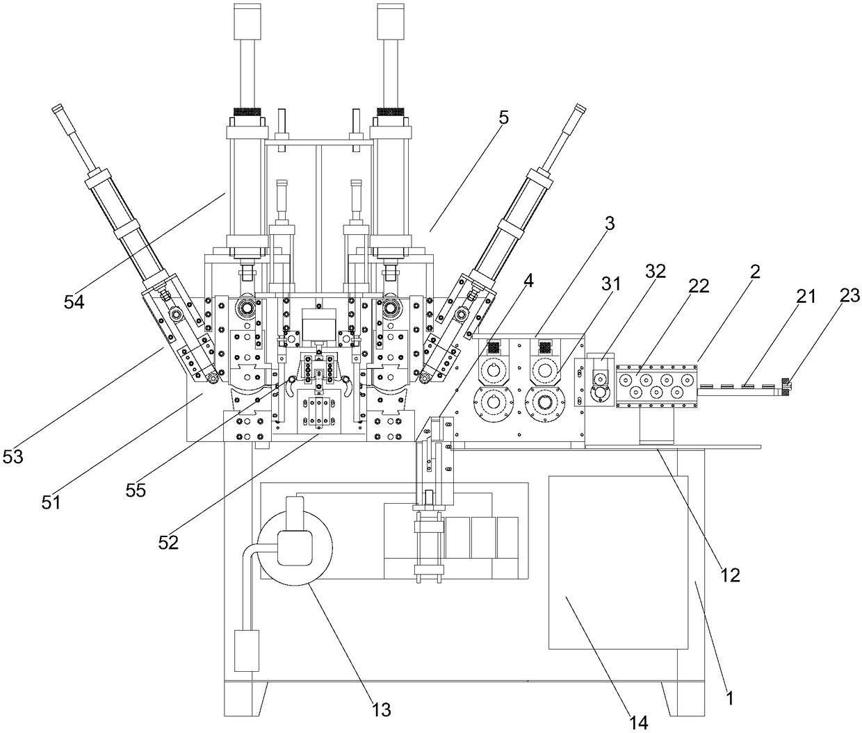
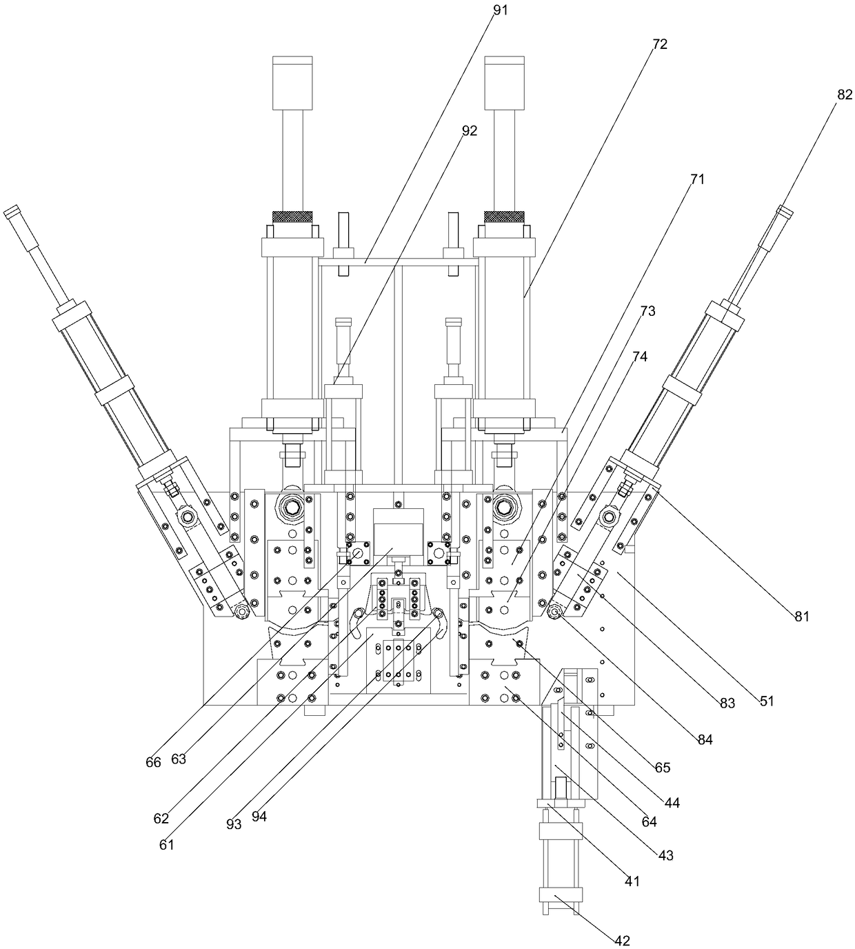
[0018] Such as Figure 1-Figure 2 As shown, the gantry structure line forming machine of the present invention includes a frame 1 and an operating table 12 installed on the frame 1, a driving part 13, and a control part 14. The side of the operating table 12 is provided with an opposite Reel-type wire straightening and flattening wire adjustment mechanism 2, the wire adjustment mechanism 2 includes a horizontal pressure roller set 21 and a longitudinal pressure roller set 22, the pressure of the horizontal pressure roller set 21 and the longitudinal pressure roller set 22 The wire openings are on the same horizontal plane, the wire inlet end of the horizontal pressure roller group 21 is provided with a wire nozzle 23, and the wire outlet end of the wire adjustment mechanism 2 is located on the operating table 12, and a wire wire mechanism 3 for conveying wire rods is installed. The above-mentioned wire mechanism 3 is installed on the main board between the rolling mechanism 5 ...


PUM


Abstract

The invention belongs to the technical field of wire rolling equipment, in particular to a wire forming machine of a portal frame structure. The wire forming machine comprises a rack, an operation panel, a driving part and a control part, wherein the operation panel, the driving part and the control part are installed on the rack, and a wire adjusting mechanism which is used for straightening andflattening a coiled wire is arranged on one side of the operation panel; a wire guide mechanism which is used for conveying the wire is installed on the wire outlet end of the wire adjusting mechanismand is located on the operation panel; a rolling mechanism which is used for pressing and forming the wire is installed on the wire outlet end of the wire guide mechanism and is located on the operation panel; and a wire cutting mechanism which is used for cutting the wire at equal lengths is installed between the rolling mechanism and the wire guide mechanism and is located on the rack. The wireforming machine has the advantages of high continuity, the reasonable structure, convenience in operation and high safety factor and is favorable for mass production of enterprises, a neutral position can be avoided in a production process, and high efficiency of a production line is guaranteed.

Description

technical field [0001] The invention belongs to the technical field of wire rod rolling equipment, in particular to a gantry structure wire forming machine. Background technique [0002] With the continuous improvement of people's living standards, the daily necessities and small furniture in the family have gradually changed from practical effects to artistic forms, especially for small objects. A shelf for placing sheet-shaped objects is mainly composed of multiple gantry frames. The steel wires of the structure are welded by stacking the main line. Its structure is simple and the storage items are highly recognizable so that it is easy to select the required items. Take out the wire from the reel material and cut it straight; then put the wire into the wire bending machine to bend both sides of the wire; put the bent wire into the punching machine to punch the arc near the bend; finally put The semi-finished wire is placed on the U-shaped mold for the gantry forming proc...

Claims


Application Information

Patent Timeline
Patent Type & Authority Applications(China)
IPC IPC(8): B21F1/02B21F11/00B21F1/00B21F23/00
CPCB21F1/004B21F1/026B21F11/00B21F23/00
Inventor 陈良旺吴恩来
Owner 徐州奔蓝机械科技有限公司
Why Eureka
Try Eureka