
Efficient welding equipment

A welding equipment and high-efficiency technology, applied in welding equipment, welding equipment, auxiliary welding equipment and other directions, can solve the problems of increased time cost, unfavorable welding efficiency, and inability to make full use of it, to improve the degree of automation, improve the utilization rate of time and Processing efficiency, the effect of shortening the time taken

Pending Publication Date: 2019-03-22
奇昊汽车系统(苏州)有限公司
View PDF0 Cites 4 Cited by
  • Summary
  • Abstract
  • Description
  • Claims
  • Application Information

AI Technical Summary

Problems solved by technology

[0002] In the field of automobile processing, it is necessary to fix nuts to various parts for subsequent assembly. When welding nuts to parts, a worker usually places the nuts and workpieces to be welded on the bearing jig first, and manually or Confirm whether the nut is placed incorrectly through the inspection equipment. After the confirmation is correct, manually start the welding machine for welding. After the welding is completed, the material is cut manually or through automatic equipment. In such a welding process, the workpiece and the nut are always located on a load-bearing fixture. In the process of nut error-proof detection, welding and automatic blanking, the staff often can only wait and cannot make full use of the time required for each processing procedure, resulting in an increase in time cost, which is not conducive to the improvement of welding efficiency
[0003] Moreover, during the welding process, the loading, welding machine start-up, and unloading operations are all operated by one worker, and the labor intensity is high.

Method used


Image

  • Efficient welding equipment
  • Efficient welding equipment
  • Efficient welding equipment

Examples


Embodiment Construction

[0028] Objects, advantages and features of the present invention will be illustrated and explained by the following non-limiting description of preferred embodiments. These embodiments are only typical examples of applying the technical solutions of the present invention, and all technical solutions formed by adopting equivalent replacements or equivalent transformations fall within the protection scope of the present invention.

[0029] In the description of the scheme, it should be noted that the terms "center", "upper", "lower", "left", "right", "front", "rear", "vertical", "horizontal", " The orientation or positional relationship indicated by "inner", "outer", etc. is based on the orientation or positional relationship shown in the drawings, and is only for the convenience of description and simplification of description, rather than indicating or implying that the device or element referred to must have a specific orientation , constructed and operated in a particular or...


PUM


Abstract

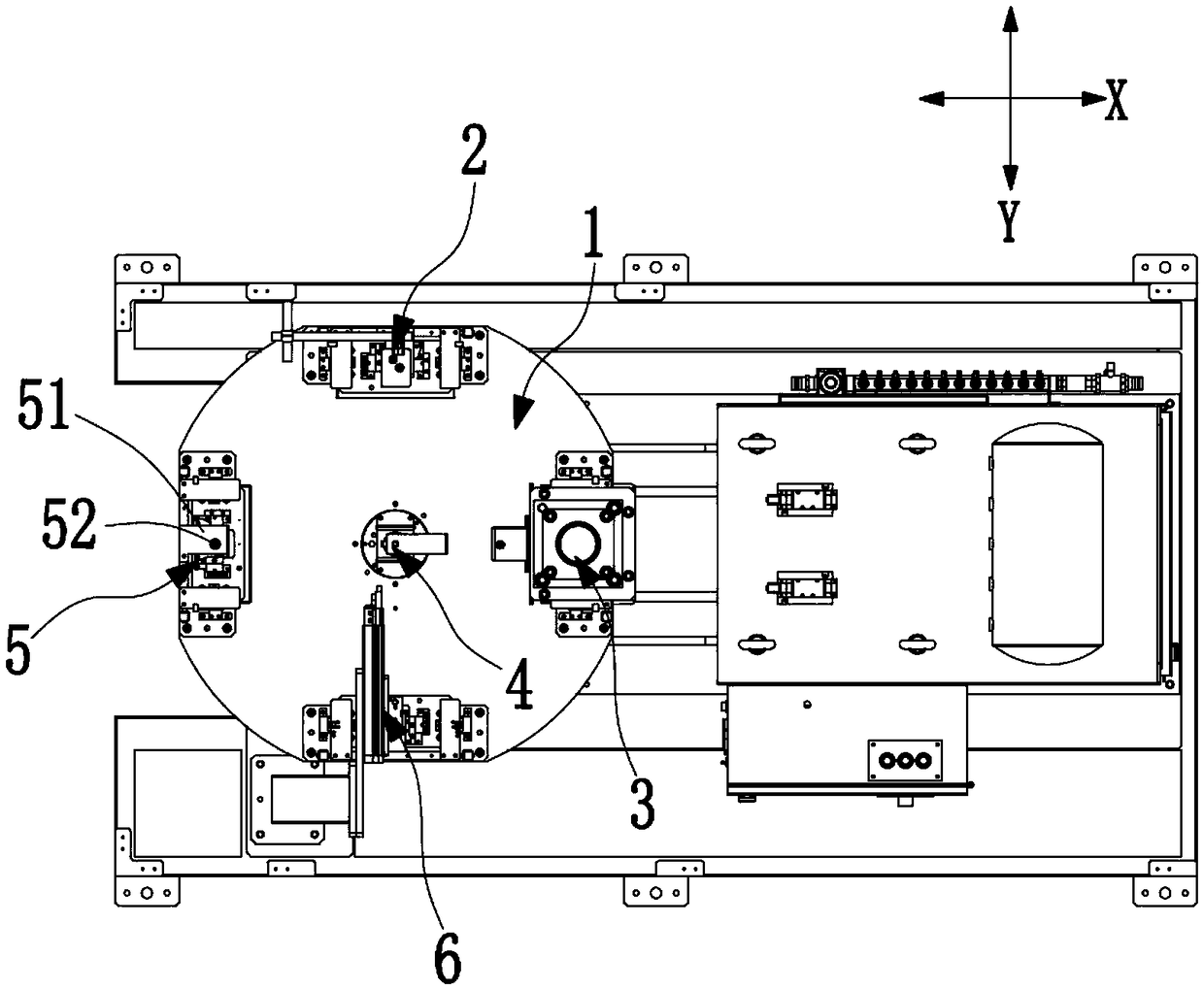
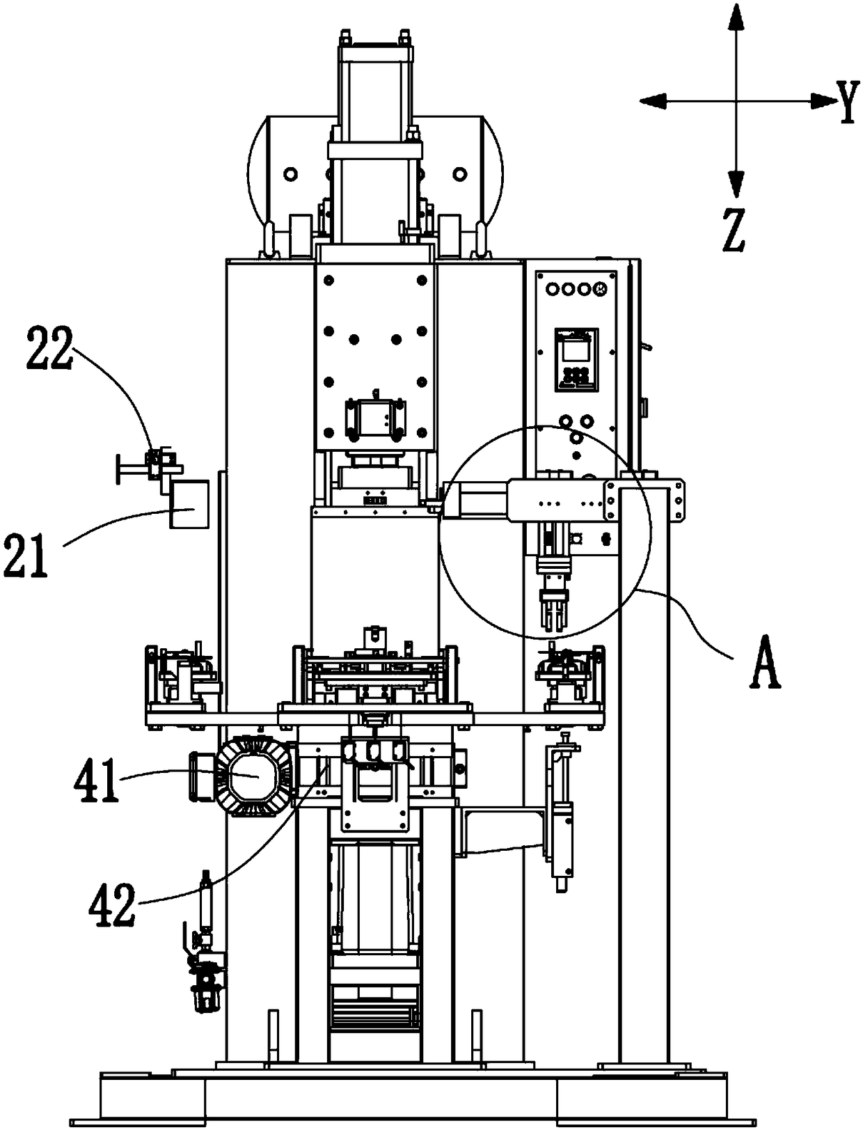
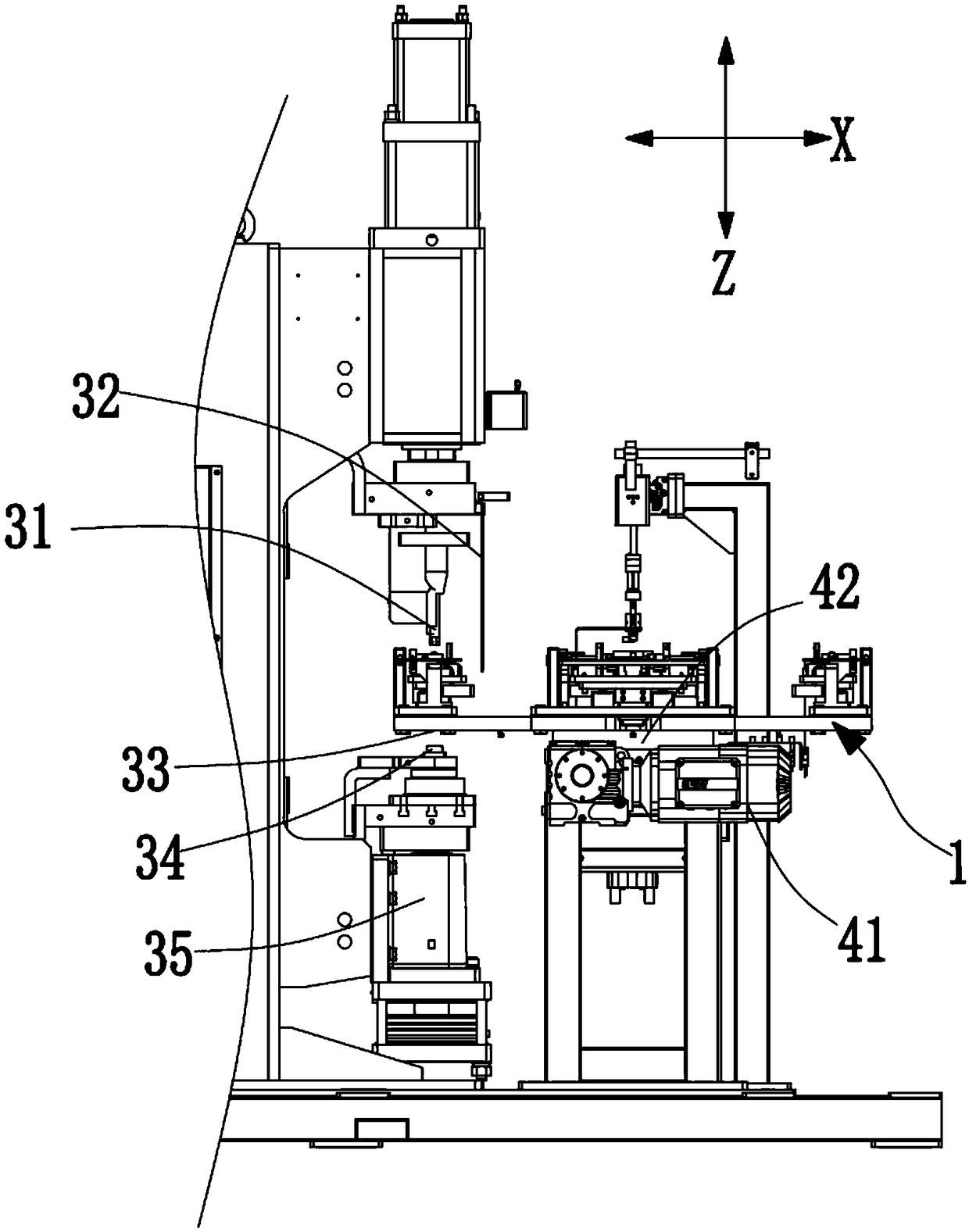
The invention discloses efficient welding equipment The efficient welding equipment comprises a rotary disc, a nut error-proofing detection device and a convex welding machine, wherein the rotary discis connected with a rotary disc driving device which drives the rotary disc to achieve autorotation around the axis of the rotary disc, at least four material loading tables which equally divide therotary disc are arranged on the top surface of the rotary disc, and each material loading table comprises turning plates capable of overturning towards the outer side of the rotary disc and a positioning pin used for positioning the nut and penetrating through the turning plates. When the nut error-proofing detection device corresponds to the position of one turning plate, the convex welding machine corresponds to the position of another adjacent turning plate. According to the welding equipment, the design is ingenious, the structure is simple, and a plurality of material loading tables are arranged on the rotary disc capable of achieving autorotation, so that a workpiece on one material loading table can be welded when feeding, discharging and detecting operations are carried out on other material loading tables, the time for welding one single workpiece can be effectively shortened, the utilization rate of time is increased, and the processing efficiency is improved. Meanwhile, workers are only responsible for feeding procedures, other procedures are automatically carried out, the labor intensity is low, and the automation degree is improved.

Description

technical field [0001] The present invention relates to welding equipment, especially high-efficiency welding equipment. Background technique [0002] In the field of automobile processing, it is necessary to fix nuts to various parts for subsequent assembly. When welding nuts to parts, a worker usually places the nuts and workpieces to be welded on the bearing jig first, and manually or Confirm whether the nut is placed incorrectly through the inspection equipment. After the confirmation is correct, manually start the welding machine for welding. After the welding is completed, the material is cut manually or through automatic equipment. In such a welding process, the workpiece and the nut are always located on a load-bearing fixture. In the process of nut error-proof detection, welding and automatic blanking, the staff often can only wait and cannot make full use of the time required for each processing procedure, resulting in an increase in time cost, which is not conduci...

Claims


Application Information

Patent Timeline
IPC IPC(8): B23K37/047B23K11/14
CPCB23K11/14B23K37/047
Inventor 陈照富倪舟
Owner 奇昊汽车系统(苏州)有限公司
Learn More